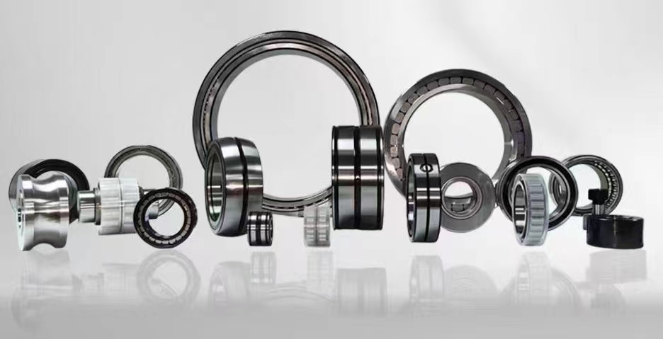
Motor Bearing Insulation: Essential Guide to Prevent Electrical Damage
Bearing insulation is a critical engineering solution designed to prevent electrical current from passing through rolling element bearings in electric motors, generators, and other rotating machinery. When stray currents travel through bearings, they can cause electrical discharge machining (EDM), leading to pitting, fluting, and premature failure. Proper bearing insulation blocks these currents, extending equipment life, reducing downtime, and improving overall system reliability in industrial applications.
1、What is bearing insulation and why is it important2、Types of insulated bearings and their applications
3、Common causes of motor bearing failure from electrical currents
4、How to test bearing insulation resistance effectively
5、Bearing insulation vs shaft grounding rings comparison
6、Installation best practices for insulated bearings
1、What is bearing insulation and why is it important
Bearing insulation refers to the deliberate incorporation of non-conductive materials or coatings into a bearing assembly to prevent the flow of electrical current between the bearing's inner ring, outer ring, rolling elements, and the surrounding housing or shaft. In modern industrial environments, particularly those utilizing variable frequency drives (VFDs), electrical currents can be induced into the motor shaft through capacitive coupling, magnetic imbalance, or common-mode voltages. Without proper insulation, these currents seek the path of least resistance through the bearing, creating microscopic arcs that erode the raceway surfaces over time. This phenomenon, known as electrical pitting or fluting, dramatically reduces bearing life from tens of thousands of hours to just a few hundred hours in severe cases. The importance of bearing insulation cannot be overstated: it directly protects capital equipment investments, minimizes unplanned production stoppages, reduces maintenance costs, and enhances operational safety. Industries such as oil and gas, power generation, mining, and manufacturing rely heavily on insulated bearings to maintain continuous operation in critical rotating machinery. Additionally, bearing insulation plays a vital role in preventing lubricant degradation caused by electrical arcing, which can lead to increased friction, elevated operating temperatures, and accelerated wear. By implementing proper bearing insulation strategies, engineers can achieve significant improvements in equipment reliability and overall plant efficiency. Furthermore, bearing insulation is not a one-size-fits-all solution; it requires careful consideration of operating conditions, voltage levels, shaft speeds, and environmental factors to select the most appropriate insulation method. Whether through ceramic coatings, hybrid ceramic bearings, or insulating sleeves, the goal remains the same: to create a robust electrical barrier that protects bearings from damaging stray currents while maintaining mechanical performance and load-carrying capacity.
2、Types of insulated bearings and their applications
The market offers several distinct types of bearing insulation solutions, each designed to address specific operational challenges and application requirements. The most common type is the hybrid ceramic bearing, which features ceramic rolling elements (typically silicon nitride) combined with steel rings. Ceramic balls are inherently non-conductive, providing excellent electrical insulation while offering superior hardness, lower thermal expansion, and reduced friction compared to conventional steel balls. Hybrid ceramic bearings are widely used in high-speed applications such as spindle motors, vacuum pumps, and traction motors where electrical protection and performance are equally critical. Another popular option is the coated bearing, where a thin layer of ceramic or polymer material is applied to the outer diameter, inner diameter, or both surfaces of the bearing ring. Aluminum oxide (Al2O3) and plasma-sprayed ceramic coatings are commonly used for their high dielectric strength and durability. These coated bearings are cost-effective solutions for standard motor applications and can be retrofitted into existing equipment. Insulating sleeves made from fiberglass-reinforced epoxy or PTFE materials represent another category, where the insulation is provided by a separate component mounted between the bearing and the housing or shaft. These sleeves offer flexibility in design and can be easily replaced without changing the bearing itself. For extreme voltage environments, fully insulated bearings with complete encapsulation in insulating materials are available, though they are less common due to higher costs. The selection of bearing insulation type depends on factors such as operating voltage, frequency, shaft speed, load conditions, temperature range, and space constraints. In VFD-driven motors operating at voltages above 480V, hybrid ceramic bearings are often preferred for their superior insulation properties and long service life. For lower voltage applications or where cost is a primary concern, coated bearings provide adequate protection. In large generators and high-power motors, insulating sleeves combined with standard bearings offer a practical compromise between performance and maintainability. Each application requires careful analysis to determine the most suitable insulation solution, considering not only electrical protection but also mechanical compatibility, thermal expansion, and environmental resistance. Engineers must also evaluate potential failure modes such as coating delamination, ceramic ball fracture under shock loads, or sleeve degradation due to chemical exposure to ensure long-term reliability.
3、Common causes of motor bearing failure from electrical currents
Electrical current-induced bearing failure is one of the most prevalent yet preventable causes of premature motor breakdown in industrial settings. Understanding the root causes is essential for implementing effective bearing insulation strategies. The primary culprit is the use of variable frequency drives (VFDs), which generate high-frequency common-mode voltages through their switching operations. These voltages couple capacitively into the motor shaft, creating a potential difference between the shaft and ground. When this voltage exceeds the dielectric breakdown threshold of the bearing's lubricant film, typically around 1-3 volts, electrical discharge occurs through the bearing, resulting in microscopic craters on the raceway surfaces. This phenomenon is known as electrical discharge machining (EDM) and manifests as pitting, frosting, or fluting patterns on the bearing components. Another common cause is magnetic asymmetry in the motor, which can induce circulating currents in the shaft. This occurs due to manufacturing tolerances, uneven air gaps, or saturation effects in the stator laminations. These low-frequency circulating currents can be substantial, reaching tens of amperes in large motors, and cause rapid overheating and damage to bearings. Shaft grounding issues also contribute significantly to bearing electrical damage. When the motor shaft is not properly grounded through a dedicated grounding brush or ring, stray currents are forced to find alternative paths through the bearings, coupling to the housing and then to ground. This is particularly problematic in motors with non-conductive couplings or when the driven equipment provides an inadequate ground path. Additionally, electrostatic charging from belt-driven systems or fluid flow can create static voltage buildup on the shaft, leading to sudden discharges through the bearings. The severity of electrical bearing damage depends on several factors including voltage magnitude, frequency, current density, lubricant properties, and bearing operating conditions. High-frequency currents tend to cause fine pitting, while low-frequency currents produce more severe fluting with distinct washboard patterns. The progression of damage typically follows a predictable pattern: initial micro-pitting gradually develops into macroscopic fluting, which then leads to increased vibration, noise, and ultimately catastrophic bearing failure. Recognizing these failure mechanisms is crucial for selecting appropriate bearing insulation solutions and implementing preventive measures such as shaft grounding, filtered output reactors, and insulated bearings to mitigate the damaging effects of electrical currents on motor bearings.
4、How to test bearing insulation resistance effectively
Testing bearing insulation resistance is a critical diagnostic procedure that helps identify potential electrical path issues before they lead to catastrophic bearing failure. The most common method involves using a megohmmeter, also known as an insulation resistance tester, which applies a high DC voltage (typically 500V or 1000V) to measure the resistance between insulated components. For hybrid ceramic bearings, the test is performed between the inner and outer rings, with the bearing mounted in its housing or on a test fixture. A minimum insulation resistance of 1 megohm is generally considered acceptable, though many applications require values exceeding 100 megohms for optimal protection. For coated bearings, the test measures resistance between the coated surface and the opposing metallic component, such as between the bearing outer diameter and the housing bore. It is important to note that insulation resistance measurements can vary significantly with temperature, humidity, and surface contamination. Therefore, tests should be conducted under controlled conditions, preferably at room temperature with clean, dry surfaces. Another effective testing method is the capacitance test, which measures the capacitance between the bearing rings. This test is particularly useful for detecting thin coating layers or early signs of insulation degradation. A sudden increase in capacitance often indicates moisture ingress or coating damage. For field testing of installed bearings, specialized bearing current probes can detect the presence of electrical discharge activity without requiring disassembly. These probes measure high-frequency current pulses that indicate EDM events occurring within the bearing. Vibration analysis can also provide indirect evidence of electrical bearing damage, as the characteristic fluting patterns produce distinct vibration signatures at bearing defect frequencies. Regular testing intervals should be established based on operating conditions, criticality of the application, and historical failure patterns. For VFD-driven motors in harsh environments, monthly insulation resistance testing is recommended, while less critical applications may require only quarterly or annual testing. When performing tests, it is essential to follow proper safety procedures, including de-energizing equipment, discharging capacitive components, and using appropriate personal protective equipment. Test results should be documented and trended over time to identify gradual degradation patterns that may indicate impending failure. Additionally, comparative testing between identical bearings or motors can help establish baseline values and identify outliers that require further investigation. By implementing a systematic bearing insulation testing program, maintenance teams can proactively identify issues, schedule repairs during planned outages, and avoid costly unplanned downtime caused by electrical bearing failure.
5、Bearing insulation vs shaft grounding rings comparison
The debate between bearing insulation and shaft grounding rings represents a fundamental engineering decision in protecting rotating machinery from electrical damage. Both approaches aim to prevent harmful currents from passing through bearings, but they operate on entirely different principles with distinct advantages and limitations. Bearing insulation, as the name suggests, creates a physical electrical barrier that blocks current flow through the bearing itself. This can be achieved through ceramic coatings, hybrid ceramic bearings, or insulating sleeves. The primary advantage of bearing insulation is that it completely eliminates the current path through the bearing, providing definitive protection regardless of external grounding conditions. However, this approach does not address the underlying issue of shaft voltage buildup; it merely redirects the problem to other components such as connected equipment or couplings. In contrast, shaft grounding rings provide a low-impedance path to ground for shaft currents, preventing voltage buildup before it can discharge through bearings. These rings typically consist of conductive fibers or brushes that maintain continuous contact with the rotating shaft, safely diverting currents to the motor frame and earth ground. The main advantage of shaft grounding rings is that they address the root cause by eliminating shaft voltage, protecting not only the motor bearings but also any connected equipment bearings. They are also generally less expensive than insulated bearings and can be retrofitted to existing motors without modification. However, shaft grounding rings require regular maintenance to ensure proper contact, as fiber wear, contamination, or oxidation can reduce effectiveness over time. In many applications, the optimal solution is a combination of both methods: using insulated bearings on one end of the motor and a shaft grounding ring on the other end. This hybrid approach provides redundant protection and ensures that even if one system fails, the other continues to protect critical components. For VFD-driven motors operating at high switching frequencies, particularly those above 1000V, both insulated bearings and shaft grounding rings are often specified as standard practice. The choice between the two methods depends on several factors including motor size, operating voltage, criticality of the application, maintenance capabilities, and budget constraints. Small motors under 100 horsepower may be adequately protected with shaft grounding rings alone, while large generators and critical process pumps often require insulated bearings for maximum reliability. Engineers should conduct a thorough risk assessment considering failure consequences, operating environment, and lifecycle costs to determine the most appropriate protection strategy for each specific application.
6、Installation best practices for insulated bearings
Proper installation of insulated bearings is paramount to achieving their intended electrical protection performance and ensuring long service life. The first critical step is verifying that the bearing's insulation properties are intact before installation. This involves measuring insulation resistance with a megohmmeter and documenting baseline values for future comparison. During handling, insulated bearings require special care to avoid damaging the coating or ceramic surfaces. Never use impact tools or hammers directly on insulated bearings, as this can crack ceramic coatings or fracture ceramic balls. Instead, use hydraulic presses or induction heaters specifically designed for bearing installation. When mounting insulated bearings onto shafts, ensure that the shaft surface is clean, smooth, and free from burrs or sharp edges that could damage the inner ring coating. For bearings with insulation on the outer diameter, the housing bore must also be prepared with appropriate surface finish and cleanliness. It is crucial to follow the manufacturer's specifications for interference fits, as excessive press fits can stress the insulation layer and reduce its dielectric strength. For coated bearings, the coating thickness is typically only 0.1 to 0.3 millimeters, making it vulnerable to damage from improper handling or installation. Temperature considerations are equally important during installation. Induction heaters should be set to the correct temperature range specified by the bearing manufacturer, typically between 80°C and 120°C for insulated bearings. Overheating can degrade the insulation properties of coatings or cause thermal stress cracking in ceramic materials. Conversely, when using cooling methods for outer ring mounting, avoid extreme cold that could cause condensation and moisture ingress into the insulation layer. During assembly, ensure that all grounding paths are properly established according to the design specifications. If the insulated bearing is intended to block current on one side of the motor, verify that the opposite bearing or shaft grounding system provides an effective alternative path. After installation, perform a final insulation resistance test to confirm that the bearing's electrical properties have not been compromised during the installation process. Additionally, check for proper alignment and clearance, as misalignment can create uneven load distribution that accelerates wear and potentially damages the insulation. For motors equipped with insulated bearings, it is also important to inspect and maintain the shaft grounding system regularly, as a well-functioning grounding system reduces the overall electrical stress on the insulated bearings. Documentation of installation procedures, test results, and any deviations from manufacturer recommendations should be maintained for quality assurance and future troubleshooting. By following these best practices, maintenance teams can maximize the effectiveness of bearing insulation investments and achieve the extended equipment life and reliability that these advanced components are designed to deliver.
In summary, the seven critical aspects of bearing insulation covered in this guide provide a comprehensive framework for understanding and implementing effective electrical protection for rotating machinery. From understanding what bearing insulation is and why it matters, to exploring the different types available, identifying common failure causes, testing methods, comparing insulation versus grounding approaches, and mastering installation best practices, each element plays an essential role in preventing electrical damage to bearings. Whether you are dealing with VFD-induced currents, magnetic imbalances, or electrostatic discharge, proper bearing insulation combined with appropriate shaft grounding strategies can dramatically extend equipment life, reduce maintenance costs, and improve operational reliability. By applying the knowledge gained from these key areas, engineers and maintenance professionals can make informed decisions that protect their critical assets and ensure continuous industrial production.
This comprehensive guide has explored the most important dimensions of bearing insulation, providing you with actionable insights to protect your motors and rotating equipment from electrical damage. By understanding the causes of bearing failure, selecting the right insulation type, implementing proper testing protocols, and following installation best practices, you can significantly extend the service life of your bearings and minimize costly downtime. Whether you are designing new systems or retrofitting existing equipment, the principles outlined here will help you achieve optimal electrical protection for your most critical machinery assets.



 8613869596835