Insulation Bearing: Essential Guide to Electrical Isolation in Motors and Generators
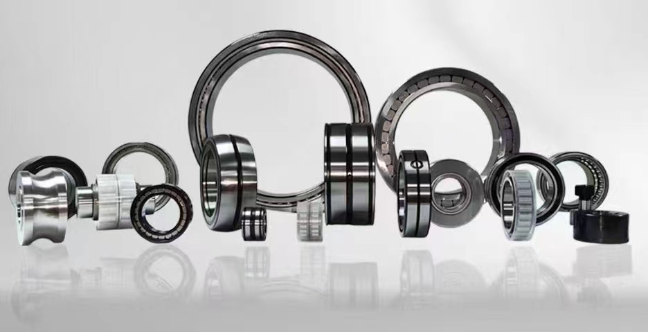
An insulation bearing is a specialized rolling element bearing designed to prevent the passage of electrical current through the bearing system. By incorporating a non-conductive layer or using ceramic rolling elements, these bearings effectively block stray shaft currents that can cause electrical discharge machining (EDM), leading to fluting, pitting, and premature failure. They are critical components in electric motors, generators, wind turbines, and variable frequency drive (VFD) applications, ensuring equipment reliability and extending service life.
1. Insulation Bearing for Electric Motors2. Hybrid Ceramic Insulation Bearing
3. Insulated Bearing Failure Causes
4. Shaft Current Protection Bearing
5. Insulation Bearing Installation Guide
6. Generator Insulated Bearing Types
1. Insulation Bearing for Electric Motors
Electric motors, especially those driven by variable frequency drives (VFDs), are highly susceptible to induced shaft voltages. These voltages seek the path of least resistance to ground, often passing through the motor bearings. When the voltage exceeds the dielectric breakdown strength of the lubricating oil film, an electrical discharge occurs. This discharge, known as electrical discharge machining (EDM), creates microscopic craters on the bearing raceways and rolling elements. Over time, these craters develop into a washboard-like pattern called fluting, which generates noise, vibration, and ultimately bearing failure. An insulation bearing for electric motors provides a high-impedance barrier that blocks these currents. The most common design features a thin, bonded ceramic coating on the outer diameter (OD) or inner diameter (ID) of the bearing ring. This coating, typically aluminum oxide (Al2O3) or a similar dielectric material, offers excellent electrical insulation resistance, usually exceeding 1000 megaohms. By installing an insulated bearing on the non-drive end (NDE) of the motor, the current path is interrupted, forcing the shaft voltage to dissipate through other safe paths, such as a grounding brush or shaft grounding ring. This simple yet effective solution dramatically reduces bearing failure rates in motor applications, particularly in industries like HVAC, pumping, conveyor systems, and manufacturing. Proper selection of the insulation type is crucial; motors with high-frequency switching inverters may require bearings with specific voltage withstand ratings to handle repetitive transient spikes. Regular inspection of the insulation coating for cracks or damage is also recommended, as any breach can compromise the insulation capability. In summary, using an insulation bearing in electric motors is a proactive maintenance strategy that directly addresses the root cause of electrically induced bearing damage, ensuring longer motor life and reduced downtime.
2. Hybrid Ceramic Insulation Bearing
The hybrid ceramic insulation bearing represents a premium solution for demanding electrical isolation requirements. Unlike traditional all-steel bearings, hybrid bearings combine steel inner and outer rings with ceramic rolling elements, typically made from silicon nitride (Si3N4). Silicon nitride is an electrical insulator with high hardness, low density, and excellent thermal properties. The ceramic balls provide inherent electrical insulation because they do not conduct electricity. This design effectively breaks the electrical circuit through the bearing, preventing current flow from the inner ring to the outer ring via the rolling elements. Hybrid ceramic bearings offer several advantages over coated steel bearings. First, the insulation is intrinsic to the material itself, not a surface coating, so it cannot peel, chip, or wear away over time. Second, ceramic balls generate less friction and heat, allowing for higher speed operation and reduced lubricant degradation. Third, they are lighter than steel balls, which reduces centrifugal forces and skidding at high speeds. However, hybrid bearings are generally more expensive than coated alternatives. They are ideal for applications where maximum reliability is critical, such as in wind turbine generators, high-speed spindles, traction motors for electric vehicles, and medical imaging equipment like MRI machines where magnetic fields are present. One important consideration is that while the ceramic balls provide insulation, the steel rings themselves can still be subject to current passage if the shaft voltage finds another path, such as through the cage or if the bearing is mounted in a conductive housing. Therefore, hybrid ceramic bearings are often used in combination with other insulation methods, such as an insulated housing or a shaft grounding system, to provide complete protection. Their long service life and consistent performance make them a cost-effective choice over the total lifecycle of critical equipment.
3. Insulated Bearing Failure Causes
Despite the robust design of insulation bearings, failures can still occur if they are not properly selected, installed, or maintained. Understanding the common failure causes is essential for maximizing bearing life. One primary cause is mechanical damage to the insulation coating. In coated bearings, the thin ceramic layer can be cracked or chipped during installation if excessive force is applied, or if the bearing is pressed onto a shaft with a rough surface. Even a small scratch can create a conductive path, allowing current to bypass the insulation and cause EDM damage. Another frequent issue is contamination of the lubricant with conductive particles. Metal debris from gear wear, carbon dust from brushes, or moisture ingress can reduce the lubricant's dielectric strength, enabling current to pass through the bearing even if the coating is intact. Electrical overstress is another failure mode. If the shaft voltage exceeds the rated breakdown voltage of the insulation layer, a puncture can occur, permanently damaging the coating. This is more common in applications with high-frequency voltage spikes from VFDs. Thermal cycling can also cause differential expansion between the steel ring and the ceramic coating, leading to delamination over time. Additionally, incorrect bearing selection plays a role; using a standard insulated bearing in an application with excessive axial or radial loads can cause the coating to crack under stress. Finally, improper grounding of the motor shaft can force all the current through the insulated bearing, overwhelming its capacity. To prevent failures, always follow manufacturer installation guidelines, use appropriate tools, ensure clean lubricant, and verify that the insulation resistance is within specification during routine maintenance. Monitoring vibration and temperature can also provide early warning signs of developing issues. By addressing these potential failure causes, the reliability of insulation bearings can be significantly enhanced.
4. Shaft Current Protection Bearing
The term "shaft current protection bearing" is often used interchangeably with insulation bearing, but it more specifically refers to bearings designed to mitigate the damaging effects of shaft currents in rotating machinery. Shaft currents can be induced by several mechanisms: magnetic asymmetry in the motor, electrostatic charging from belt drives, or high-frequency common-mode voltages from VFDs. Regardless of the source, the result is the same: electrical erosion of bearing surfaces. A shaft current protection bearing functions as a dedicated barrier that blocks or diverts these currents. There are two main approaches: using an insulated bearing to block the current, or using a conductive bearing in combination with an external grounding device. For many applications, the insulated bearing is the preferred method because it provides passive, maintenance-free protection. These bearings are specifically engineered to withstand the voltage levels and frequency characteristics common in industrial motors and generators. They are often tested to meet international standards such as IEC 60034-17, which outlines methods for evaluating bearing insulation. When selecting a shaft current protection bearing, engineers must consider the maximum expected shaft voltage, the operating speed, and the environmental conditions. For very high voltages or harsh environments, a hybrid ceramic bearing may be necessary. In some designs, the outer ring is coated with a thick layer of insulation material, and the bearing is mounted in an insulating sleeve or housing to provide additional protection. The key performance metric is the insulation resistance, which should be measured periodically using a megohmmeter. A drop in resistance below the manufacturer's threshold indicates a potential failure. By integrating shaft current protection bearings into the design phase of new equipment or as a retrofit solution, maintenance teams can dramatically reduce unscheduled downtime and repair costs associated with bearing failures.
5. Insulation Bearing Installation Guide
Proper installation of an insulation bearing is critical to ensure its long-term performance and to avoid damaging the delicate insulation layer. The following step-by-step guide outlines best practices. First, always inspect the bearing upon receipt. Check the packaging for damage and ensure the bearing model matches the specification. Handle the bearing with clean, dry gloves to avoid contaminating the surfaces. Before installation, measure the insulation resistance using a 500V or 1000V megohmmeter. The resistance should typically be above 1000 megaohms. Record this baseline value for future comparison. For mounting, use a hydraulic press or a specialized bearing installation tool that applies force only to the ring being press-fitted. Never apply force through the rolling elements or the coated surface. If pressing the bearing onto a shaft, apply force to the inner ring only. If pressing into a housing, apply force to the outer ring only. Ensure the shaft and housing bore are clean, free of burrs, and within the specified tolerance. A tight fit is necessary to prevent rotation of the bearing ring, but excessive interference can crack the coating. Use a thin layer of oil on the mating surfaces to reduce friction during pressing. After installation, rotate the shaft by hand to check for smooth operation and listen for any unusual noise. Re-measure the insulation resistance to confirm that the coating was not damaged during mounting. Finally, ensure that any grounding brushes or other electrical paths are properly connected, as the insulation bearing alone may not protect against all current paths. For applications with high shaft voltages, consider installing an insulating coupling on the driven load to prevent current from bypassing the bearing. Regular re-testing of insulation resistance during maintenance intervals will help identify any deterioration early. Following these installation guidelines will maximize the service life of the insulation bearing and protect the connected equipment.
6. Generator Insulated Bearing Types
Generators, particularly large turbine generators and wind turbine generators, face unique challenges from shaft currents. These currents can be induced by residual magnetism, unbalanced magnetic pull, or electrostatic charging from the rotating blades. To protect generator bearings, several insulated bearing types are available. The most common is the coated bearing, where a layer of ceramic or epoxy-based insulation is applied to the outer diameter of the bearing ring. This coating is typically 0.2 to 0.5 mm thick and provides reliable insulation for moderate voltage levels. For large generators, a more robust solution is the insulated bearing with a separate insulating sleeve. In this design, the bearing is mounted inside a non-conductive sleeve made from materials like fiberglass-reinforced epoxy or PTFE. This sleeve provides both mechanical support and electrical isolation. Another type is the hybrid ceramic bearing, which uses ceramic rolling elements for intrinsic insulation. This type is favored in high-speed generators where reduced friction and heat generation are beneficial. For very large turbine generators, special insulated bearings with multiple layers of insulation and advanced sealing systems are used to withstand high axial and radial loads while maintaining electrical isolation. The selection of the correct type depends on factors such as generator size, voltage rating, operating speed, and environmental conditions. For wind turbine generators, which experience variable loads and harsh weather, hybrid ceramic bearings are often chosen for their reliability and long maintenance intervals. In hydroelectric generators, coated bearings with enhanced corrosion resistance are common. Regardless of the type, all generator insulated bearings must be tested to meet stringent industry standards, such as those from IEEE or IEC. Regular monitoring of bearing insulation resistance and vibration is essential to ensure the generator operates safely and efficiently over its intended lifespan. By choosing the appropriate insulated bearing type, generator operators can prevent costly failures and maintain high availability.
This guide has explored six critical aspects of insulation bearings: their use in electric motors, the advanced technology of hybrid ceramic bearings, common failure causes and how to avoid them, the role of shaft current protection, detailed installation procedures, and the various types available for generators. From coated bearings that provide a cost-effective barrier against electrical discharge to hybrid ceramic bearings that offer intrinsic, long-lasting insulation, each solution addresses the fundamental problem of stray shaft currents. Understanding how to select the right bearing, install it correctly, and monitor its condition is essential for protecting valuable rotating equipment. Whether you are an engineer designing a new motor, a maintenance technician troubleshooting a failure, or a procurement specialist sourcing components, the knowledge of insulation bearings empowers you to make informed decisions that enhance reliability and reduce operational costs. The prevention of electrical pitting and fluting is not just about bearing longevity; it is about ensuring the continuous operation of critical machinery in industries ranging from manufacturing to renewable energy. By integrating the insights from this article into your maintenance and design practices, you can effectively mitigate the risks posed by shaft currents and extend the life of your equipment.
In conclusion, insulation bearings are indispensable components in modern electrical machinery, providing a reliable solution to the pervasive problem of shaft currents. We have covered the fundamental concept of electrical isolation, the specific applications in motors and generators, the distinct advantages of hybrid ceramic and coated designs, and the practical steps for installation and failure prevention. The key takeaway is that proper selection and maintenance of insulation bearings directly translate to reduced downtime, lower repair costs, and improved equipment efficiency. As industries continue to adopt variable frequency drives and high-efficiency motors, the demand for effective electrical insulation in bearings will only grow. By staying informed about the latest technologies and best practices, you can ensure that your machinery operates safely and reliably for years to come. Remember that an investment in quality insulation bearings is an investment in the overall health of your rotating equipment.



 8613869596835