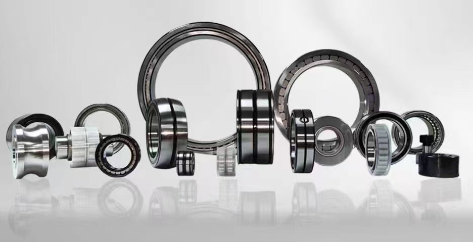
High-Load Cylindrical Roller Thrust Bearings: Design, Applications, and Selection Guide
Cylindrical roller thrust bearings are specialized rolling-element bearings designed to accommodate axial loads in one direction while permitting high-speed operation. Unlike standard radial bearings, these thrust bearings utilize cylindrical rollers arranged in a cage, providing exceptional load-carrying capacity and rigidity. They are essential components in heavy machinery, gearboxes, and industrial transmissions where high axial forces and moderate speeds are present. Their unique design minimizes friction and heat generation, ensuring long service life and reliable performance under demanding conditions.
1. cylindrical roller thrust bearing design
2. thrust roller bearing vs ball bearing
3. high load thrust bearing applications
4. cylindrical thrust bearing catalogue
5. axial load bearing selection guide
1. cylindrical roller thrust bearing design
The design of cylindrical roller thrust bearings is a masterpiece of engineering precision, optimized for handling pure axial loads with minimal friction. At the core of this design lies a set of cylindrical rollers, typically made from high-carbon chromium steel, arranged radially between two washer-like raceways. One raceway is flat and stationary, while the other is slightly crowned or tapered to guide the rollers and ensure uniform load distribution. The rollers are held in place by a machined brass or polyamide cage, which prevents skewing and reduces noise during operation. The number and diameter of the rollers directly influence the bearing's dynamic and static load ratings. A typical design incorporates a single row of rollers for moderate loads, but for extreme axial forces, double-row or multi-row configurations are available. The rollers have a length-to-diameter ratio carefully calculated to maximize contact area without generating excessive heat. Surface finishing is critical; raceways and rollers are ground and super-finished to achieve sub-micron tolerances, reducing vibration and extending fatigue life. Lubrication channels or grooves are often integrated into the shaft washer to facilitate oil or grease flow, essential for high-speed applications. The design also accounts for thermal expansion, with axial clearances set to accommodate temperature variations. Advanced finite element analysis (FEA) is used to optimize roller profiling, minimizing edge stress and preventing premature failure. In modern designs, ceramic rollers are sometimes employed for higher speeds and resistance to corrosion. The simplicity of the cylindrical shape allows for easy manufacturing and inspection, making these bearings both cost-effective and highly reliable. Engineers must also consider the housing and shaft fit tolerances, as improper mounting can distort the raceways and reduce performance. Overall, the cylindrical roller thrust bearing design is a balance of strength, durability, and efficiency, tailored for specific industrial demands.
2. thrust roller bearing vs ball bearing
When comparing thrust roller bearings to thrust ball bearings, the fundamental difference lies in the type of rolling elements and their resulting performance characteristics. Thrust roller bearings, including cylindrical roller variants, use elongated rollers that provide line contact with the raceways, whereas thrust ball bearings use spherical balls that create point contact. This line contact in roller bearings allows them to support significantly higher axial loads, often ten times or more than equivalent-sized ball bearings. For example, a cylindrical roller thrust bearing with a 100mm bore can handle static axial loads exceeding 500 kN, while a ball thrust bearing of similar size might only manage 50 kN. However, ball bearings excel in high-speed applications because point contact generates less friction and heat. Thrust ball bearings can operate at speeds up to 10,000 RPM, while cylindrical roller thrust bearings are generally limited to 3,000-5,000 RPM due to centrifugal forces and lubrication challenges. Another key difference is rigidity: roller bearings offer greater stiffness, making them ideal for applications requiring precise axial positioning, such as machine tool spindles. Ball bearings, on the other hand, have lower stiffness but can accommodate slight misalignment more easily. Lubrication requirements also differ: roller bearings demand continuous oil flow for high-speed operations, while ball bearings can often run with grease. In terms of cost, roller bearings are generally more expensive due to complex manufacturing. Maintenance intervals vary as well: roller bearings typically require more frequent inspection because roller skewing can cause edge loading. For applications like heavy presses, crane hooks, or marine propellers, cylindrical roller thrust bearings are the clear choice. For light-duty, high-speed applications like automotive clutches or small pumps, ball thrust bearings are preferred. Understanding these trade-offs is crucial for proper bearing selection, ensuring optimal performance and longevity in any axial load scenario.
3. high load thrust bearing applications
High load thrust bearings, particularly cylindrical roller thrust bearings, are indispensable in heavy industries where massive axial forces must be managed reliably. One of the most common applications is in large gearboxes used for mining conveyors, cement mills, and crushers. These gearboxes experience extreme axial loads from helical and bevel gears, and cylindrical roller thrust bearings provide the necessary rigidity to maintain gear alignment and prevent tooth failure. Another critical application is in marine propulsion systems, where the thrust from the propeller must be transmitted to the ship's hull without damaging the engine. Here, multi-row cylindrical roller thrust bearings are installed in the thrust block to handle axial forces exceeding 1,000 kN. In the oil and gas sector, these bearings are used in mud pumps and draw works on drilling rigs, where high pressure and shock loads are common. The bearings must withstand not only static axial loads but also dynamic fluctuations during operation. In wind turbines, the main shaft and gearbox rely on cylindrical roller thrust bearings to handle the axial thrust generated by the rotor blades. These bearings operate in harsh environments with temperature extremes and limited access for maintenance, so durability is paramount. Heavy-duty presses for metal forming also employ these bearings in the slide and ram assemblies, where they support the full press tonnage. Additionally, they are found in railway rolling stock, specifically in the axle boxes of locomotives, where they manage the axial forces during braking and cornering. In the aerospace sector, cylindrical roller thrust bearings are used in helicopter rotor heads and landing gear mechanisms, where weight and reliability are critical. Even in smaller applications like hydraulic pumps and compressors, these bearings handle the axial component of the helical rotors. The key to their widespread use is the ability to customize roller length, diameter, and material to match specific load requirements. As industries push for higher power densities and longer service intervals, the demand for optimized high load thrust bearings continues to grow.
4. cylindrical thrust bearing catalogue
A comprehensive cylindrical thrust bearing catalogue is an essential tool for engineers and procurement specialists, providing detailed technical data to facilitate accurate selection. Leading manufacturers such as SKF, NSK, FAG, and Timken publish catalogues that list bearing series like the 811, 812, and 893 families, each designed for specific load and speed ranges. The catalogue typically begins with a dimensional chart, including bore diameter (d), outer diameter (D), and height (H) in millimeters, along with the corresponding weight. For example, the 81120 series has a bore of 100mm, outer diameter of 135mm, and height of 25mm, with a dynamic load rating of 160 kN. Following dimensions, the catalogue provides load ratings: basic dynamic load rating (Ca) and static load rating (C0a), which are critical for calculating bearing life using the ISO L10 formula. Speed ratings are also listed as limiting speeds for oil and grease lubrication. Another important section covers tolerances, typically P0 (normal) and P6 (higher precision), along with radial runout and axial runout values. The catalogue includes mounting and dismounting guidelines, recommended fits for shaft and housing, and minimum axial load requirements to prevent roller skidding. Lubrication recommendations are detailed, specifying viscosity grades and oil flow rates for oil bath or circulating systems. Many catalogues now include online search tools that allow filtering by load, speed, and dimensions. Cross-reference tables help identify equivalent bearings from different manufacturers. Special variants like sealed or coated bearings for corrosive environments are also listed. The catalogue often features application examples, such as the use of 893 series bearings in screw compressors or 811 series in crane hooks. Technical appendices cover calculation methods for equivalent dynamic load, life adjustment factors for reliability and material, and installation torque values for locking nuts. For custom applications, some catalogues offer design templates for modified roller profiles or special cages. Having access to a reliable catalogue ensures that the right cylindrical thrust bearing is chosen, avoiding costly failures and downtime.
5. axial load bearing selection guide
Selecting the correct axial load bearing involves a systematic evaluation of operating conditions, load characteristics, and environmental factors. The first step is to determine the magnitude and direction of the axial load. For pure axial loads in one direction, cylindrical roller thrust bearings are ideal. If there are combined radial and axial loads, a tapered roller bearing or spherical roller bearing might be necessary. Next, calculate the equivalent dynamic load (P) considering any shock loads or vibrations, using factors from ISO 281. For example, if the actual axial load is 200 kN with moderate shock, a factor of 1.5 yields a design load of 300 kN. Then, select a bearing with a dynamic load rating (Ca) at least 1.5 times the design load to ensure a reasonable L10 life of 10,000 to 50,000 hours. Speed is another critical factor: cylindrical roller thrust bearings have limiting speeds typically between 1,000 and 3,000 RPM for standard sizes. If speeds exceed this, consider using a thrust ball bearing or a special high-speed roller bearing with ceramic rollers. Lubrication method influences selection: for oil bath lubrication, the oil level must cover the lowest roller; for circulating oil, flow rate and viscosity must be calculated. Temperature range affects material choice: standard bearings operate from -30°C to +120°C, while high-temperature variants use special steels and heat treatments. Space constraints in the housing and shaft dimensions must be checked against the bearing envelope. For example, a shaft diameter of 80mm would typically pair with a bearing having a 80mm bore, but the outer diameter must fit the housing. Mounting orientation also matters: vertical shafts require locking devices to prevent axial movement. Finally, consult the manufacturer's catalogue for specific recommendations on fits, tolerances, and preload. For critical applications, consider using double-row or paired bearings for higher load capacity and redundancy. Always verify the static load safety factor (fs = C0a / F0a) to prevent plastic deformation during peak loads. By following this axial load bearing selection guide, engineers can ensure optimal performance, reliability, and cost-efficiency in any thrust application.
To help you navigate the world of cylindrical roller thrust bearings, this article has covered five key aspects: design principles, comparison with ball bearings, high-load applications, catalogue resources, and a selection guide. Understanding the unique geometry of cylindrical rollers and their ability to handle extreme axial loads is fundamental for any engineer. The comparison with ball bearings highlights the trade-off between load capacity and speed, guiding you to the right choice for your machinery. Real-world applications in mining, marine, wind energy, and heavy presses demonstrate the versatility and robustness of these components. A thorough catalogue provides the technical data needed for precise selection, while the selection guide offers a step-by-step methodology to match bearing specifications with operational demands. Whether you are designing a new gearbox or upgrading an existing system, these insights will help you achieve longer bearing life, reduced maintenance, and improved equipment reliability. Cylindrical roller thrust bearings remain a cornerstone of modern industrial engineering, and mastering their use is essential for any professional involved in mechanical design or maintenance.
In conclusion, cylindrical roller thrust bearings are vital components for handling high axial loads in a wide range of industrial applications. From their robust design featuring precision-ground rollers and hardened raceways to their superior load capacity compared to ball bearings, these bearings offer unmatched reliability. Whether you are selecting a bearing from a catalogue, evaluating high-load applications, or following an axial load bearing selection guide, the key is to match the bearing's capabilities with your specific operational conditions. Proper installation, lubrication, and maintenance will further extend service life. As industries continue to demand higher performance and durability, cylindrical roller thrust bearings will remain an essential solution for axial load management. By leveraging the information in this guide, you can make informed decisions that enhance machinery efficiency and reduce downtime, ensuring long-term success in your engineering projects.



 8613869596835