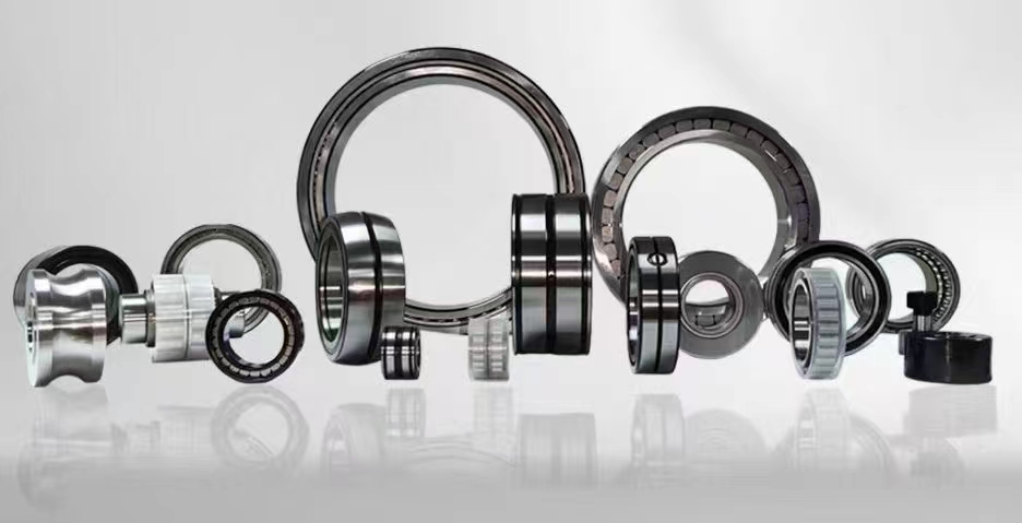
Insulation Bearing Applications: A Comprehensive Guide to Electrical Insulation in Rotating Machinery
Insulation bearings are specialized rolling element bearings designed to prevent the passage of electrical current through the bearing system. By incorporating a dielectric layer or non-conductive rolling elements, these bearings block electrical discharge machining (EDM) currents that can cause pitting, fluting, and premature failure in motors, generators, and industrial equipment. Insulation bearings are essential in variable frequency drive (VFD) applications, wind turbines, and railway traction systems where shaft voltages are common.
1、Insulated bearing types2、Bearing insulation material
3、Shaft current prevention
4、Electrical pitting bearing failure
5、VFD bearing protection
6、Ceramic coated bearing
7、Hybrid ceramic bearing
1、Insulated bearing types
There are several distinct types of insulation bearings engineered to address different levels of electrical threat and application requirements. The most common category is the coated insulation bearing, where a thin ceramic layer, typically aluminum oxide (Al2O3), is applied to the outer or inner ring surfaces using plasma spray or physical vapor deposition (PVD) technology. These coatings provide dielectric strength ranging from 500 to 1000 volts DC, making them suitable for general industrial motors and small generators. Another major type is the hybrid ceramic bearing, which features silicon nitride (Si3N4) ceramic balls combined with steel rings. The ceramic balls act as natural insulators, breaking the electrical circuit completely. Hybrid bearings offer superior performance in high-speed applications and are widely used in machine tool spindles and aerospace equipment. A third category is the fully insulated bearing, where both rings are made of non-conductive materials or are encapsulated in insulating housings. These are employed in extreme environments such as electrolytic cells and medical imaging equipment where even minimal leakage currents cannot be tolerated. Each type has specific advantages in terms of load capacity, speed rating, temperature tolerance, and cost. Selecting the correct insulation bearing type requires careful analysis of shaft voltage levels, operating frequency, lubrication conditions, and mechanical load characteristics. Manufacturers like SKF, NSK, and FAG offer standardized insulation bearing series with documented performance data to simplify selection.
2、Bearing insulation material
The effectiveness of an insulation bearing depends critically on the properties of the insulating material used. For coated bearings, aluminum oxide (Al2O3) is the most widely adopted material due to its excellent dielectric strength of approximately 15-20 kV/mm, high hardness (1800-2000 HV), and good thermal conductivity. The coating thickness typically ranges from 100 to 300 micrometers, with thicker coatings providing higher voltage breakdown resistance but potentially affecting bearing geometry and running accuracy. Advanced coatings now incorporate zirconia (ZrO2) or titanium dioxide (TiO2) to improve adhesion and reduce porosity. For hybrid ceramic bearings, silicon nitride (Si3N4) is the preferred rolling element material. It offers a density about 40% lower than steel, which reduces centrifugal forces at high speeds, combined with a hardness of 1400-1700 HV and fracture toughness superior to other ceramics. Si3N4 balls also exhibit excellent thermal stability up to 800°C and are resistant to corrosive environments. In fully insulated bearing designs, polymeric materials such as polyetheretherketone (PEEK) or thermoset composites are used for cage and housing insulation. These materials provide high dielectric strength and chemical resistance but have lower mechanical strength compared to ceramics. The choice of bearing insulation material must balance electrical performance against mechanical reliability, thermal expansion compatibility, and manufacturing cost. Recent developments include nano-ceramic composite coatings that achieve dielectric strengths exceeding 2000 volts while maintaining coating thickness below 100 microns, enabling insulation bearings to be used in compact motor designs.
3、Shaft current prevention
Shaft current prevention is the primary function of insulation bearings in rotating machinery. Shaft currents, also known as bearing currents, are induced when magnetic flux asymmetries in electric motors and generators create a voltage potential between the rotor shaft and the motor frame. These voltages can range from a few volts to over 30 volts in VFD-driven systems, and when the voltage exceeds the breakdown threshold of the lubricating oil film (typically 0.1-1.0 volt per micrometer), electrical discharge occurs through the bearing. Each discharge creates a microscopic crater on the raceway surface, gradually developing into fluting patterns that generate noise, vibration, and ultimately bearing seizure. Insulation bearings prevent this by introducing a high-impedance path that blocks current flow. The most effective prevention strategy involves using an insulation bearing on the non-drive end of the motor while maintaining a conductive path to ground through the drive-end bearing and shaft grounding systems. This configuration, known as hybrid grounding, reduces the circulating current loop and minimizes bearing damage. For large motors above 100 kW, it is common practice to install insulation bearings on both ends combined with shaft grounding brushes or conductive grease seals. Proper shaft current prevention also requires attention to cable routing, shielding, and filter installation on VFD output terminals. High-frequency common-mode currents, which can bypass insulation bearings through parasitic capacitance, must be managed using ferrite cores or common-mode chokes. Routine monitoring of bearing vibration and shaft voltage using oscilloscopes or dedicated bearing current sensors helps verify the effectiveness of shaft current prevention measures over the equipment lifecycle.
4、Electrical pitting bearing failure
Electrical pitting bearing failure is a distinct damage mechanism caused by repeated electrical discharges through the bearing interface. Unlike mechanical wear or fatigue failure, electrical pitting manifests as a series of small craters or pits on the rolling element surfaces and raceways, often arranged in a washboard-like pattern known as fluting. The formation process begins when the lubricant film thickness becomes insufficient to insulate the contact surfaces, allowing a spark to jump across the gap. Each spark generates localized temperatures exceeding 1000°C, melting and vaporizing a tiny volume of steel. Over thousands of such events, the surface becomes roughened, leading to increased friction, elevated operating temperatures, and accelerated lubricant degradation. In VFD applications, electrical pitting can occur within weeks of operation if no protective measures are implemented. The characteristic fluting pattern produces a distinct tonal noise that increases with motor speed, often described as a whining or screeching sound. Vibration analysis reveals harmonics at the bearing defect frequencies, typically concentrated in the 1-10 kHz range. Prevention of electrical pitting bearing failure requires a combination of insulation bearings, shaft grounding systems, and conductive greases. For existing equipment showing early signs of electrical pitting, replacing standard bearings with insulation bearings is the most effective corrective action. The cost of bearing replacement is far lower than the downtime and repair costs associated with catastrophic bearing seizure or rotor damage. Regular inspection using borescopes or magnetic particle testing can detect pitting at an early stage, allowing maintenance teams to intervene before failure occurs.
5、VFD bearing protection
Variable frequency drive (VFD) bearing protection is critical because VFDs are the primary source of shaft voltages in modern industrial systems. VFDs generate pulse-width modulated (PWM) waveforms with fast voltage rise times (dv/dt) ranging from 1000 to 10000 volts per microsecond. These steep transitions induce common-mode voltages on the motor shaft through capacitive coupling between the stator windings and the rotor. The resulting shaft voltages can reach 20-40 volts peak-to-peak, far exceeding the dielectric strength of conventional bearing lubricants. VFD bearing protection strategies must address both low-frequency circulating currents and high-frequency capacitive discharge currents. Insulation bearings are the first line of defense, but they must be complemented by other measures for comprehensive protection. Shaft grounding rings, which use conductive fibers to provide a low-impedance path to ground, are effective for diverting high-frequency currents away from bearings. Ceramic discharge suppression filters installed at the VFD output terminals reduce dv/dt and peak voltage levels. For severe applications, such as those involving long cable runs between VFD and motor, sine-wave filters or dV/dt reactors are recommended. The selection of grease also plays a role in VFD bearing protection; conductive greases containing carbon black or metal particles provide a parallel current path that reduces the voltage across the bearing. However, conductive greases may increase friction and require more frequent relubrication. Modern VFD bearing protection systems often incorporate real-time monitoring of bearing current using current transformers, with alarms triggered when current levels exceed safe thresholds. Proper grounding of the motor frame, VFD enclosure, and cable shields according to IEEE 142 standards is essential to prevent ground loops that can exacerbate bearing currents.
6、Ceramic coated bearing
Ceramic coated bearings represent a cost-effective insulation solution for applications where full hybrid ceramic bearings are not economically justified. The ceramic coating, usually aluminum oxide (Al2O3), is applied to the outer ring outer diameter (OD) or inner ring bore using advanced thermal spray or PVD processes. The coating creates a dense, adherent dielectric layer with typical thickness of 100-300 micrometers. One key advantage of ceramic coated bearings is their compatibility with standard bearing geometries and mounting procedures. They can be directly substituted for conventional bearings in existing equipment without housing modifications. The dielectric strength of a ceramic coated bearing typically exceeds 1000 volts DC, sufficient for most industrial motor applications up to 690V. However, the coating is vulnerable to mechanical damage during installation if improper mounting tools or excessive force are used. Special care must be taken to avoid pressing the coated surface against sharp edges or using hammers. Another consideration is thermal expansion: the ceramic layer has a lower coefficient of thermal expansion than steel, which can cause micro-cracking under extreme temperature cycling. To mitigate this, manufacturers apply the coating at elevated temperatures and use bond coatings to improve adhesion. Ceramic coated bearings are available in standard ISO and ANSI dimensions, making them drop-in replacements for common bearing series such as 6200, 6300, and 7200 series. Performance testing shows that ceramic coated bearings can extend motor bearing life by 3-5 times compared to standard bearings in VFD applications. They are also effective in preventing electrical pitting in DC motors, wind turbine generators, and traction motors. The cost premium for ceramic coated bearings over standard bearings is typically 30-50%, which is justified by the extended service life and reduced maintenance costs.
7、Hybrid ceramic bearing
Hybrid ceramic bearings combine steel inner and outer rings with ceramic rolling elements, typically silicon nitride (Si3N4) balls. This design offers superior electrical insulation because the ceramic balls have virtually zero electrical conductivity, breaking the current path through the bearing completely. Beyond electrical insulation, hybrid ceramic bearings provide several additional performance advantages. The lower density of ceramic balls (approximately 3.2 g/cm3 versus 7.8 g/cm3 for steel) reduces centrifugal forces at high speeds, allowing higher operating speeds without skidding. Ceramic balls also have a higher elastic modulus, resulting in less deformation under load and improved stiffness. This makes hybrid ceramic bearings ideal for precision applications such as machine tool spindles, where runout must be maintained within 1-2 micrometers. The thermal properties of silicon nitride are also beneficial: it has a thermal expansion coefficient about one-third that of steel, which reduces internal clearance changes with temperature. Hybrid ceramic bearings can operate at temperatures up to 800°C, far exceeding the limits of standard steel bearings. In terms of lubrication, ceramic balls have a lower coefficient of friction against steel raceways, reducing operating temperatures and extending grease life. The main limitation of hybrid ceramic bearings is their higher initial cost, typically 2-4 times that of standard bearings. However, in applications where electrical pitting is a concern, the total cost of ownership is often lower due to extended bearing life and reduced downtime. Hybrid ceramic bearings are also more resistant to contamination because ceramic balls are harder than steel and less susceptible to denting from debris. They are commonly used in VFD-driven motors, electric vehicle traction systems, and high-speed compressors. When selecting hybrid ceramic bearings, engineers must consider the cage material (usually PEEK or brass) and the need for proper handling to avoid thermal shock damage during installation.
From the seven key aspects explored above, including insulation bearing types, bearing insulation materials, shaft current prevention strategies, electrical pitting failure mechanisms, VFD protection methods, ceramic coated bearings, and hybrid ceramic bearings, it is clear that insulation bearings are indispensable for modern rotating machinery. Whether you are designing a new motor system or retrofitting existing equipment, understanding these insulation bearing concepts helps ensure reliable operation, extended equipment life, and reduced maintenance costs. The choice between coated and hybrid bearings depends on your specific voltage levels, speed requirements, and budget constraints.
In summary, insulation bearings play a vital role in protecting rotating equipment from electrical damage caused by shaft currents and VFD-induced voltages. By selecting the appropriate insulation bearing type based on your application requirements, implementing proper grounding and filtering systems, and performing regular monitoring, you can prevent electrical pitting failures and maximize the service life of motors, generators, and industrial machinery. The ongoing development of advanced ceramic coatings and hybrid ceramic technologies continues to expand the capabilities of insulation bearings, making them an increasingly important component in energy-efficient and high-reliability systems.



 8613869596835