Insulation Bearing: The Ultimate Guide to Electrical Isolation and Motor Protection
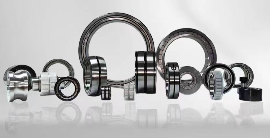
An insulation bearing is a specialized rolling element bearing designed to prevent the passage of electrical current through the bearing system. By incorporating a ceramic coating, hybrid ceramic materials, or insulating layers, these bearings block stray electrical currents that can cause arcing, pitting, and premature failure in electric motors, generators, and other rotating machinery. Insulation bearings are critical for extending equipment lifespan and reducing unplanned downtime in industrial applications.
1、electrically insulated bearing2、bearing insulation resistance
3、hybrid ceramic bearing
4、shaft grounding vs insulated bearing
5、VFD bearing protection
6、motor bearing failure causes
7、insulated bearing installation
1、electrically insulated bearing
An electrically insulated bearing is a critical component in modern industrial machinery, specifically designed to block the flow of electrical current through the bearing assembly. These bearings typically feature a specialized ceramic coating applied to the outer or inner ring, or utilize hybrid ceramic rolling elements made from silicon nitride. The primary function is to prevent electrical discharge machining (EDM) currents from damaging the bearing raceways and rolling elements. In variable frequency drive (VFD) applications, high-frequency common-mode voltages can induce shaft currents that seek the path of least resistance through the bearing. Without insulation, these currents create micro-welding and fluting damage, leading to vibration, noise, and catastrophic failure. Electrically insulated bearings maintain high resistance values, often exceeding 1000 megohms, ensuring reliable operation in harsh electrical environments. Industries such as wind energy, railway traction, automotive manufacturing, and industrial pumping heavily rely on these bearings to protect expensive equipment. The insulation layer is engineered to withstand extreme temperatures, humidity, and mechanical stress without degrading. Proper selection of the insulation type, whether coated ring or hybrid ceramic, depends on the specific voltage levels, shaft speed, and load conditions. Regular inspection of insulation resistance using a megohmmeter is recommended to ensure ongoing protection. By implementing electrically insulated bearings, facilities can significantly reduce maintenance costs, extend motor life, and improve overall system reliability. The growing adoption of VFDs and high-efficiency motors has made insulated bearings a standard requirement in many OEM specifications and retrofitting projects.
2、bearing insulation resistance
Bearing insulation resistance is a key performance metric that determines the effectiveness of an insulation bearing in preventing electrical current flow. Measured in megohms (MΩ) using an insulation resistance tester or megohmmeter, this value indicates the quality and integrity of the insulating layer between the bearing rings. A healthy insulation bearing should exhibit resistance values typically above 500 MΩ, with many high-quality products exceeding 1000 MΩ under dry conditions. Factors that can degrade insulation resistance include moisture ingress, contamination by conductive particles, thermal cycling, mechanical damage during installation, and aging of the insulating material. In VFD-driven motors, the high-frequency switching generates capacitive coupling that can cause voltage buildup on the rotor shaft; effective bearing insulation resistance prevents this voltage from discharging through the bearing. Testing protocols often specify applying 500V or 1000V DC test voltage and measuring the resistance after 60 seconds of stabilization. It is important to note that insulation resistance can vary with temperature; higher temperatures typically reduce resistance values temporarily. Regular monitoring of bearing insulation resistance is a recommended practice in predictive maintenance programs, as a sudden drop may indicate impending failure. Standards such as ISO 15243 and IEC 60034-17 provide guidelines for acceptable insulation resistance levels. When installing new insulated bearings, verifying the initial resistance ensures the product has not been damaged during shipping or handling. In critical applications, redundant insulation systems or additional shaft grounding brushes may be used alongside insulated bearings to achieve optimal protection. Understanding and maintaining proper bearing insulation resistance is fundamental to preventing electrical bearing damage and ensuring long-term equipment reliability.
3、hybrid ceramic bearing
A hybrid ceramic bearing is a type of insulation bearing that combines ceramic rolling elements, usually silicon nitride (Si3N4), with steel inner and outer rings. This design inherently provides electrical insulation because the ceramic balls are non-conductive, preventing current from passing through the bearing. Hybrid ceramic bearings offer several distinct advantages over fully steel bearings with coated rings. The ceramic balls are harder, lighter, and have a lower coefficient of friction, resulting in reduced heat generation and higher operating speeds. They also exhibit superior corrosion resistance and can operate in lubricant-starved conditions for short periods without catastrophic failure. In terms of electrical protection, hybrid ceramic bearings provide inherent insulation without the risk of coating delamination or wear that can affect coated ring designs. They are particularly effective in high-frequency applications where capacitive coupling through the bearing is a concern. However, hybrid ceramic bearings are generally more expensive than coated steel bearings and require careful handling to avoid cracking the ceramic elements. They are widely used in precision spindles, high-speed machining centers, aerospace actuators, medical imaging equipment, and electric vehicle traction motors. The lifespan of hybrid ceramic bearings often exceeds that of conventional steel bearings by two to three times in clean, well-lubricated environments. When selecting a hybrid ceramic bearing for insulation purposes, engineers must consider the load rating, speed limits, and compatibility with the housing and shaft materials. The insulating property of the ceramic material is unaffected by temperature variations up to 800°C, making these bearings suitable for extreme thermal environments. Overall, hybrid ceramic bearings represent a high-performance solution for applications demanding both electrical insulation and mechanical excellence.
4、shaft grounding vs insulated bearing
The comparison between shaft grounding and insulated bearing systems is essential for engineers designing protection against electrical bearing damage. Shaft grounding, typically achieved through carbon brushes, conductive fiber brushes, or grounding rings, provides a low-resistance path for shaft currents to bypass the bearings and return to ground. Insulated bearings, on the other hand, block the current from entering the bearing entirely by creating a high-resistance barrier. Both methods aim to prevent electrical discharge machining (EDM) damage, but they operate on different principles and have distinct advantages and limitations. Shaft grounding systems are effective at diverting low-frequency and high-frequency currents but can wear out over time, requiring periodic brush replacement or cleaning. They also introduce mechanical friction and debris into the system. Insulated bearings provide a maintenance-free solution with no wearing parts, but they rely on the integrity of the insulating layer, which can be compromised by contamination or damage. In many modern VFD applications, a combination of both methods is employed: insulated bearings on the drive end and shaft grounding on the non-drive end, or vice versa, depending on the motor design. The choice between the two depends on factors such as motor size, shaft voltage levels, operating environment, maintenance capabilities, and cost considerations. For small to medium motors (under 100 kW), insulated bearings alone are often sufficient. For larger motors or those with high shaft voltages, shaft grounding plus insulated bearings on both ends may be necessary. Studies have shown that properly implemented shaft grounding can reduce bearing currents by over 90%, while insulated bearings can eliminate them entirely when the insulation resistance remains high. The decision should be based on a thorough analysis of the electrical environment, including common-mode voltage measurements, bearing current detection, and risk assessment. Consulting with bearing manufacturers and electrical engineers is recommended to design the optimal protection strategy.
5、VFD bearing protection
Variable frequency drive (VFD) bearing protection is a critical consideration in modern motor systems, as VFDs are known to induce harmful electrical currents in motor bearings. The high-frequency switching of IGBTs in VFDs creates common-mode voltages that capacitively couple through the motor windings to the rotor shaft. This can result in shaft voltages ranging from 10V to over 100V, depending on the drive characteristics, cable length, and motor design. When these voltages exceed the breakdown threshold of the bearing lubricant film, electrical discharge machining (EDM) occurs, causing microscopic craters in the bearing raceways. Over time, this creates a characteristic fluting pattern that leads to vibration, noise, and eventual bearing failure. The primary methods for VFD bearing protection include using insulated bearings, shaft grounding systems, Faraday shielding, conductive grease, and common-mode filters. Insulated bearings, whether coated ring or hybrid ceramic, provide a reliable barrier against current flow. Shaft grounding brushes or rings divert currents away from the bearings. Faraday shields between the stator and rotor can reduce capacitive coupling. Conductive grease lowers the impedance of the bearing, allowing currents to pass without arcing, though this may increase wear. Common-mode chokes and filters on the drive output can reduce the magnitude of high-frequency voltages. For optimal protection, many OEMs now specify insulated bearings on both motor ends for VFD applications. Standards such as NEMA MG1 and IEC 60034-17 provide guidelines for selecting bearing protection methods based on motor size and drive type. Regular monitoring of bearing currents using high-frequency current transformers (HFCT) can help detect developing problems. Proper VFD bearing protection not only extends bearing life but also improves system reliability, reduces maintenance costs, and prevents unscheduled downtime in critical processes.
6、motor bearing failure causes
Motor bearing failure causes are numerous, but electrical damage has become increasingly prevalent with the widespread adoption of variable frequency drives. The most common causes of motor bearing failure include inadequate lubrication, contamination by dirt or moisture, misalignment, overloading, fatigue, and electrical discharge machining (EDM). Among these, electrical damage is responsible for up to 40% of premature bearing failures in VFD-driven motors. Electrical bearing damage manifests as fluting, frosting, or pitting on the raceways and rolling elements, caused by the passage of electrical current through the bearing. This current can be induced by common-mode voltages from VFDs, electrostatic discharge from belt drives, or grounding issues in the electrical system. Mechanical causes such as improper installation, shaft deflection, and housing deformation can also accelerate bearing failure. Lubrication-related failures include using the wrong grease, insufficient or excessive grease, and grease degradation due to high temperatures. Contamination from abrasive particles, moisture, or corrosive chemicals can rapidly destroy bearing surfaces. Fatigue failure, which occurs after millions of stress cycles, is a natural end-of-life mechanism but can be accelerated by any of the above factors. To diagnose the root cause of motor bearing failure, engineers should examine the failure patterns on the bearing components. Fluting with a characteristic washboard pattern indicates electrical damage. Discoloration suggests overheating. Pitting with rust points to contamination. By understanding the specific failure mechanisms, appropriate corrective actions can be taken, such as installing insulation bearings, improving sealing, optimizing lubrication schedules, or correcting alignment. Implementing a comprehensive bearing protection strategy, including insulated bearings and shaft grounding where indicated, can dramatically reduce failure rates and extend motor life by two to three times in VFD applications.
7、insulated bearing installation
Insulated bearing installation requires careful attention to detail to ensure the insulating properties are maintained and the bearing performs as intended. The first step is to verify that the bearing is the correct type and size for the application, considering load, speed, and electrical requirements. Before installation, inspect the bearing for any visible damage to the insulating coating or ceramic elements. Handle insulated bearings with clean, dry gloves to avoid contaminating the insulation surface. When mounting the bearing onto the shaft, use appropriate tools such as induction heaters for steel rings or press-fit methods with proper alignment. Never apply force directly to the ceramic rolling elements of hybrid ceramic bearings. The housing bore must be clean, free of burrs, and within tolerance to avoid distorting the bearing outer ring. For coated ring bearings, ensure that the insulating layer is not damaged during pressing or hammering. Electrical continuity checks should be performed before and after installation using a megohmmeter to confirm the insulation resistance remains within specification. It is crucial that no conductive paths bypass the bearing insulation; for example, grounding straps, oil seals with conductive fibers, or metallic debris can create unintended current paths. In some designs, insulating sleeves or washers may be required to isolate the bearing housing from the end bracket. After installation, run the motor without load and measure bearing currents using a high-frequency current transformer to verify protection effectiveness. Proper lubrication with a compatible grease is essential; some greases contain conductive additives that may compromise insulation. Follow the manufacturer's recommendations for grease type and quantity. Regular maintenance inspections should include insulation resistance testing and visual examination of the bearing area for signs of electrical discharge. By following correct insulated bearing installation procedures, facilities can maximize the lifespan and reliability of their motor systems.
Throughout this guide, we have explored seven critical aspects of insulation bearings: electrically insulated bearing design, bearing insulation resistance testing, hybrid ceramic bearing advantages, the comparison between shaft grounding vs insulated bearing, VFD bearing protection strategies, common motor bearing failure causes, and proper insulated bearing installation procedures. Each of these topics is interconnected and essential for understanding how to protect rotating equipment from electrical damage. The selection of the right insulation bearing type, combined with correct installation and regular maintenance, can prevent premature bearing failure caused by stray electrical currents. Whether you choose coated ring bearings for cost-effectiveness or hybrid ceramic bearings for superior performance, the key is to match the protection method to your specific electrical environment. As VFD usage continues to grow across industries, the importance of insulation bearings will only increase. By implementing the knowledge from these seven topics, engineers and maintenance professionals can significantly reduce downtime, lower repair costs, and enhance the reliability of their motor systems.
In conclusion, insulation bearings are an indispensable solution for preventing electrical bearing damage in modern industrial applications. From understanding the basics of electrically insulated bearings to mastering the installation process, this guide has provided comprehensive coverage of the most important related search terms. The growing prevalence of variable frequency drives and the resulting shaft currents make insulation bearings a critical component for any motor-driven system. By combining the right insulation bearing technology with proper shaft grounding where needed, and by regularly monitoring insulation resistance, you can achieve optimal protection against bearing current damage. Remember that prevention is always more cost-effective than repair. Investing in high-quality insulation bearings and following best practices for installation and maintenance will pay dividends through extended equipment life, improved energy efficiency, and reduced unplanned downtime. We encourage you to consult with bearing manufacturers and electrical specialists to develop a tailored protection strategy for your specific applications, ensuring your operations remain reliable and productive for years to come.



 8613869596835