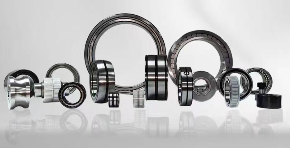
Essential Guide to Bearing Thrust: Types, Loads, Applications, and Selection
Bearing thrust refers to the axial load acting parallel to the shaft axis that bearings must support in rotating machinery. Understanding thrust loads is critical for selecting the correct bearing type, ensuring proper installation, and preventing premature failure. This guide covers thrust bearing fundamentals, load calculations, common types like angular contact and tapered roller bearings, and best practices for maintenance.
1. thrust load calculation for bearings
2. angular contact ball bearing thrust capacity
3. tapered roller bearing thrust rating
4. thrust bearing installation procedure
5. bearing thrust failure analysis
6. axial load vs radial load in bearings
7. thrust bearing preload adjustment
1. thrust load calculation for bearings
Thrust load calculation for bearings is a fundamental engineering task that ensures rotating equipment operates reliably under axial forces. The thrust load, also known as axial load, is the force acting parallel to the shaft axis. To calculate this load accurately, engineers must consider both static and dynamic conditions. Static thrust load occurs when the shaft is stationary or rotating at very low speeds, while dynamic thrust load arises during normal operation with varying speeds and directions. The basic formula for thrust load (Fa) is derived from the sum of external axial forces applied to the shaft, including gear forces, propeller thrust, or axial components from belt drives. In many applications, such as vertical pumps or machine tool spindles, the weight of the rotating assembly itself contributes significantly to the thrust load. Engineers must also account for thermal expansion effects, which can induce additional axial forces as the shaft and housing materials expand at different rates. For complex systems, finite element analysis (FEA) is used to model the load distribution across multiple bearings. Once the thrust load is determined, it must be compared against the bearing's rated static and dynamic load capacities provided by the manufacturer. The static load rating (C0) prevents permanent deformation, while the dynamic load rating (C) predicts fatigue life under rotating conditions. A safety factor of 1.5 to 2.0 is commonly applied for critical applications like aerospace or medical equipment. Proper calculation prevents overloading, which leads to premature wear, overheating, and eventual bearing seizure. In multi-bearing arrangements, the thrust load is shared unevenly due to differences in stiffness and clearance, requiring iterative calculation methods. Modern bearing selection software simplifies this process by integrating load data, speed, and lubrication conditions to recommend optimal bearing configurations.
2. angular contact ball bearing thrust capacity
Angular contact ball bearings are specifically designed to handle combined radial and thrust loads, with their thrust capacity being a key performance parameter. These bearings feature raceways that are offset relative to each other in the direction of the bearing axis, allowing them to accommodate axial forces in one direction. The thrust capacity of an angular contact ball bearing depends on several factors: the contact angle, ball size and number, raceway curvature, and material hardness. Standard contact angles range from 15 degrees to 40 degrees, with larger angles providing higher thrust capacity at the expense of reduced radial load capability. For example, a 40-degree contact angle bearing can support approximately 50% more axial load than a 15-degree version of the same size. The thrust capacity is also influenced by the number of balls in the bearing assembly; more balls distribute the load over a larger contact area, increasing capacity. However, adding balls reduces the cage space and may limit lubrication flow. Manufacturers publish thrust load ratings in their catalogs, typically as static thrust load (C0a) and dynamic thrust load (Ca). These values are derived from standardized testing methods defined by ISO and ABMA standards. In practice, angular contact bearings are often used in pairs—back-to-back, face-to-face, or tandem arrangements—to handle bidirectional thrust loads. A back-to-back arrangement provides high rigidity and is common in machine tool spindles, while a tandem arrangement doubles the thrust capacity in one direction. The actual thrust capacity in a paired configuration is not simply twice the single bearing value due to load sharing effects and internal clearance adjustments. Preloading the bearing set improves stiffness and reduces vibration but reduces the effective thrust capacity because some load capacity is consumed by the preload force. Engineers must carefully calculate the required preload based on operating speed, temperature, and expected external thrust loads to maximize bearing life without exceeding the material limits.
3. tapered roller bearing thrust rating
Tapered roller bearings are renowned for their exceptional ability to support heavy combined radial and thrust loads, making them indispensable in automotive, mining, and industrial gearbox applications. The thrust rating of a tapered roller bearing is determined by its geometry, specifically the cup angle and the number and size of the tapered rollers. Unlike angular contact ball bearings, tapered roller bearings use conical rollers guided by a flange on the inner ring (cone). This design allows line contact between the rollers and raceways, providing higher load capacity per unit volume. The thrust rating is expressed as the basic dynamic axial load rating (Ca) and static axial load rating (C0a) in manufacturer catalogs. These ratings are calculated based on the bearing's internal geometry, material properties, and standardized life equations. For a given bearing series, the thrust capacity increases with larger roller diameters and longer roller lengths. The cup angle, typically ranging from 10 to 30 degrees, directly influences the thrust-to-radial load ratio. A steeper cup angle yields higher thrust capacity but reduces the bearing's ability to handle radial loads. In single-row tapered roller bearings, thrust loads must be opposed by a second bearing or a separate thrust element because the bearing can only support axial loads in one direction. When used in pairs, such as in automotive wheel hubs or pinion shafts, the total thrust rating depends on the mounting arrangement and the internal clearance set during installation. The effective thrust rating of a paired set is not simply additive due to load sharing dynamics and thermal expansion effects. Engineers must also consider the limiting speed of the bearing, as higher thrust loads increase friction and heat generation, potentially reducing the maximum allowable operating speed. Proper lubrication is critical for achieving the rated thrust capacity; insufficient oil flow or incorrect viscosity can lead to smearing, scoring, or catastrophic failure. Modern tapered roller bearings often incorporate optimized roller profiles and surface finishes to enhance thrust performance under heavy loads and high speeds.
4. thrust bearing installation procedure
Correct thrust bearing installation is essential for achieving the designed load capacity, service life, and operational reliability. The procedure varies depending on bearing type—angular contact, tapered roller, or spherical thrust bearing—but follows universal principles. First, ensure the shaft and housing are clean, free of burrs, and within specified tolerances for roundness and surface finish. Measure the shaft diameter and housing bore at multiple points to confirm fit class. For interference fits, use an induction heater or oil bath to expand the bearing inner ring evenly; never apply heat directly with a torch as it damages the material. For tapered roller bearings, install the cone (inner ring with rollers) onto the shaft using a mounting sleeve and press, ensuring the cone seats fully against the shaft shoulder. The cup (outer ring) is then pressed into the housing using a suitable arbor press or hydraulic tool. Angular contact bearings require careful orientation: in a back-to-back arrangement, the load lines converge outward, providing high rigidity; in a face-to-face arrangement, load lines converge inward, allowing some misalignment. When installing multiple bearings on a single shaft, use a spacer or shim to set the correct axial clearance or preload. For preloaded systems, measure the drag torque with a torque wrench to verify the preload force is within specification. Lubrication is applied immediately after installation; grease-packed bearings need a specific quantity, while oil-lubricated systems require proper oil level and circulation. After installation, rotate the shaft by hand to check for smooth operation and listen for unusual noises. Run the equipment at low speed initially to allow the bearing to seat and distribute lubricant. Monitor temperature rise during the first hours of operation; a sudden increase indicates misalignment, excessive preload, or insufficient lubrication. Document the installation parameters, including measured clearances, preload values, and torque readings, for future maintenance reference. In critical applications like turbine generators or high-speed spindles, use vibration analysis and thermal imaging to validate installation quality before full-load operation.
5. bearing thrust failure analysis
Bearing thrust failure is a common and costly problem in rotating machinery, often resulting from misapplication, installation errors, or operating conditions beyond design limits. Analyzing failed bearings provides critical insights to prevent recurrence. Typical failure modes related to thrust loads include axial cracking, spalling on the raceway shoulders, roller end wear, and cage fracture. Axial cracking occurs when excessive thrust load causes tensile stresses exceeding the material's fatigue limit, leading to cracks propagating from the raceway surface. Spalling on the raceway shoulders is characteristic of thrust overload in angular contact and tapered roller bearings, where the load zone shifts to the edge of the raceway. Roller end wear appears as polished or galled areas on the large end of tapered rollers due to high contact pressure against the cone flange. Cage fracture often results from thrust-induced skewing of rollers or balls, causing the cage pockets to deform and break. To perform a thorough failure analysis, follow these steps: visually inspect the bearing for discoloration, scoring, and surface damage; measure residual clearance or interference; examine the raceway surfaces under magnification for fatigue patterns; and analyze the lubricant for contamination and degradation. Compare the operating conditions—speed, load, temperature, and lubrication—against the bearing manufacturer's specifications. Use finite element analysis or bearing calculation software to verify the actual thrust load applied to the bearing during operation. In many cases, the root cause is a combination of factors: a thrust load exceeding the rated capacity, misalignment causing uneven load distribution, or inadequate lubrication leading to boundary layer breakdown. Corrective actions include selecting a bearing with a higher thrust rating, redesigning the shaft and housing to improve alignment, adjusting preload settings, or upgrading the lubrication system. Implementing condition monitoring—vibration analysis, oil analysis, and thermography—enables early detection of thrust-related issues before catastrophic failure occurs. Document all findings and corrective actions in a reliability database to track recurring patterns across similar equipment.
6. axial load vs radial load in bearings
Understanding the difference between axial load and radial load is fundamental to bearing selection and application engineering. Axial load, also called thrust load, acts parallel to the shaft axis, while radial load acts perpendicular to the shaft axis. Bearings are designed to handle specific load directions and magnitudes. Deep groove ball bearings can accommodate moderate radial loads and some axial loads in both directions, but their axial capacity is limited compared to specialized thrust bearings. Cylindrical roller bearings excel at radial loads but have very limited axial capacity unless designed as NU or NJ types with flanges. Tapered roller bearings are unique in their ability to handle high combined radial and thrust loads simultaneously, with the load ratio determined by the contact angle. Angular contact ball bearings provide a balance between radial and axial capacity, with the contact angle dictating the proportion. In many applications, the ratio of axial to radial load (Fa/Fr) is a critical design parameter. For example, in a helical gear drive, the axial load can be 20-30% of the radial load, requiring a bearing that can handle both. In a vertical pump, the weight of the rotor creates a pure axial load with minimal radial component. Misapplying a bearing designed primarily for radial loads in a high-thrust application leads to rapid wear and failure. Engineers must calculate both load components using free-body diagrams and dynamic analysis, then select bearings with adequate ratings for each direction. The equivalent dynamic load (P) formula combines axial and radial loads using factors specific to each bearing type. For deep groove ball bearings, P = XFr + YFa, where X and Y are derived from the bearing geometry and load ratio. Proper load classification ensures optimal bearing life, efficiency, and reliability in rotating equipment.
7. thrust bearing preload adjustment
Thrust bearing preload adjustment is a critical process in precision rotating systems to eliminate clearance, increase stiffness, and improve running accuracy. Preload applies a permanent axial force to the bearing before any external load is applied, ensuring that rolling elements remain in constant contact with the raceways. This eliminates play and reduces vibration, which is essential for machine tool spindles, automotive differentials, and aerospace actuators. The amount of preload must be carefully calculated: too little preload results in excessive clearance and vibration, while too much preload generates high friction, heat, and premature wear. Preload adjustment methods vary by bearing type and application. For angular contact ball bearings used in pairs, preload is set by selecting bearings with specific internal clearance classes or by using spacers of precise thickness between the bearings. In tapered roller bearing sets, preload is adjusted by tightening a locknut or adjusting shims until a specified drag torque is achieved. The drag torque is measured using a torque wrench while rotating the shaft at a slow speed; typical values range from 0.1 to 2.0 Nm depending on bearing size and application. For high-speed spindles, spring preload is used to maintain constant preload despite thermal expansion; disc springs or coil springs provide a consistent axial force over a range of deflections. Hydraulic preload systems allow adjustment under operating conditions, enabling optimization for different speed and load regimes. Temperature monitoring is essential during preload adjustment because thermal expansion can increase preload beyond safe limits, causing bearing seizure. In automotive wheel bearings, preload is set using a torque-angle method: tighten the nut to a specified torque, then rotate it an additional angle to achieve the correct preload. After adjustment, verify the axial play using a dial indicator; acceptable play is typically 0.01-0.05 mm for most applications. Document the preload setting and measurement method for reproducibility during maintenance. Advanced systems use piezo-electric sensors or strain gauges to monitor preload in real-time, allowing adaptive control for optimal performance.
From thrust load calculation to preload adjustment, mastering the seven key aspects of bearing thrust covered in this guide—load calculation methods, angular contact and tapered roller capacities, installation procedures, failure analysis, axial versus radial load differentiation, and preload techniques—enables engineers to design and maintain reliable rotating machinery. Each topic provides actionable insights for selecting the right bearing, preventing common failures, and optimizing performance under demanding axial loads. Whether you are designing a new gearbox, troubleshooting a failed spindle, or specifying bearings for a vertical pump, these principles form the foundation of successful thrust bearing application. Continue exploring our resources for deeper technical data and application-specific recommendations.
Understanding bearing thrust is vital for any engineer or technician working with rotating equipment. This comprehensive guide has explored seven essential areas: thrust load calculation, angular contact ball bearing thrust capacity, tapered roller bearing thrust rating, thrust bearing installation procedure, bearing thrust failure analysis, the difference between axial and radial loads, and thrust bearing preload adjustment. Each section provides detailed technical knowledge to help you select, install, and maintain bearings for optimal performance under axial loads. By applying these concepts, you can extend equipment life, reduce downtime, and improve operational efficiency. For further assistance with bearing selection or custom engineering solutions, contact our team of application specialists.



 8613869596835