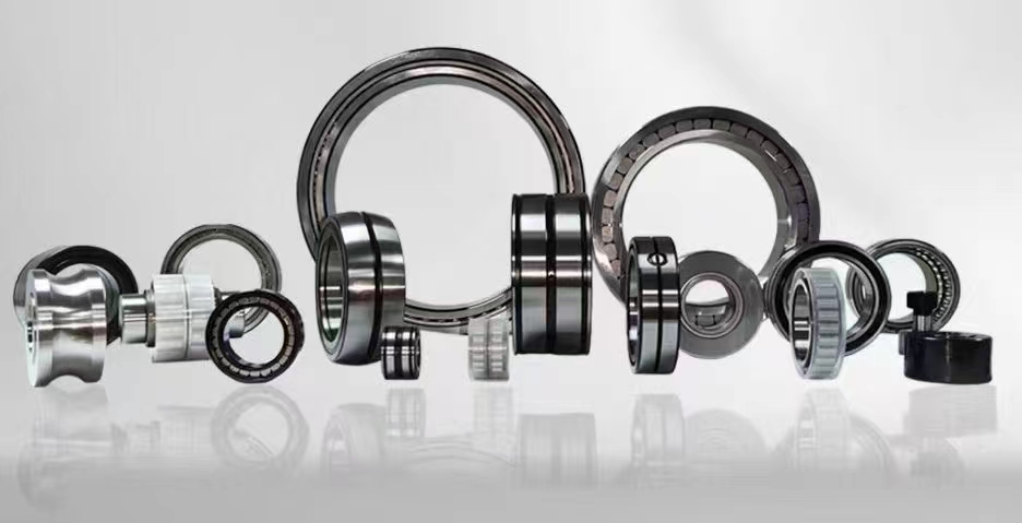
Bearing Insulation: Essential Guide for Electric Motor Protection and Reliability
Bearing insulation is a critical engineering solution designed to prevent electrical current from passing through rolling element bearings in electric motors and generators. When stray shaft currents or high-frequency voltage spikes from variable frequency drives (VFDs) discharge through bearings, they cause electrical discharge machining (EDM), leading to pitting, fluting, and premature failure. By introducing a non-conductive barrier between the bearing and its housing or shaft, insulated bearings effectively block these damaging currents, ensuring reliable operation and extending equipment lifespan.
1、Insulated Bearing2、Bearing Insulation Resistance
3、Shaft Current Prevention
4、Ceramic Coated Bearing
5、Electric Motor Bearing Protection
6、VFD Bearing Damage
1、Insulated Bearing
An insulated bearing is a specialized rolling element bearing that incorporates an electrically insulating layer to block the flow of current from the shaft to the bearing housing or vice versa. These bearings are typically manufactured with a ceramic coating applied to the outer diameter (OD) of the bearing outer ring, or in some designs, to the inner ring bore. The most common coating material is aluminum oxide (Al2O3), which provides excellent dielectric strength, typically exceeding 1000 V DC per 0.1mm of coating thickness. Insulated bearings are indispensable in applications where electrical discharge is a known risk, such as in motors driven by variable frequency drives (VFDs), generators, traction motors, and wind turbine generators. The insulation layer effectively breaks the electrical circuit that would otherwise allow stray currents to travel through the bearing. Without this barrier, even small currents can cause electrical discharge machining (EDM), creating microscopic craters on the rolling elements and raceways. Over time, these craters develop into washboard-like fluting patterns, leading to increased vibration, noise, and eventual bearing seizure. Insulated bearings come in various standard series, including deep groove ball bearings, cylindrical roller bearings, and spherical roller bearings, allowing for direct replacement of standard bearings in most motor designs. The installation process is identical to standard bearings, requiring no modifications to the housing or shaft. However, care must be taken not to damage the ceramic coating during handling or mounting. The use of insulated bearings is considered the most reliable method for protecting bearings from electrical erosion, especially in harsh industrial environments where other mitigation methods like shaft grounding brushes may wear out or fail. By investing in insulated bearings, manufacturers can significantly reduce unplanned downtime, maintenance costs, and extend the service life of critical rotating equipment by three to five times compared to non-insulated alternatives.
2、Bearing Insulation Resistance
Bearing insulation resistance is a quantitative measure of how effectively an insulated bearing blocks electrical current, typically expressed in megohms (MΩ) or gigaohms (GΩ). This parameter is crucial for verifying that the insulation layer is intact and functioning as designed. Standard insulated bearings typically offer insulation resistance values exceeding 1000 MΩ at 1000 V DC, though high-performance variants can achieve values in the GΩ range. The insulation resistance is primarily determined by the thickness, uniformity, and material properties of the ceramic coating applied to the bearing ring. Manufacturers test each bearing individually using high-voltage insulation testers (megohmmeters) to ensure compliance with industry standards such as ISO 15243 or specific customer requirements. It is important to note that insulation resistance can degrade over time due to several factors. Contamination from conductive dust, moisture ingress, or oil mist can create a conductive path across the ceramic surface, reducing the effective resistance. Additionally, mechanical damage from improper handling or mounting can crack or chip the coating, creating a direct electrical path. Regular condition monitoring should include periodic insulation resistance testing, especially in critical applications. A drop in resistance below the recommended threshold (typically 1 MΩ per kV of operating voltage) indicates potential damage or contamination and warrants immediate investigation. Field testing is performed using a megohmmeter connected between the bearing outer ring and the housing, or between the inner ring and the shaft. For accurate results, the bearing should be clean, dry, and at a stable temperature. Temperature affects insulation resistance, with higher temperatures generally reducing resistance values. Understanding and maintaining proper bearing insulation resistance is essential for preventing electrical erosion and ensuring the long-term reliability of electric motors and generators. This metric provides a clear, quantifiable indicator of insulation health and should be part of any comprehensive motor maintenance program.
3、Shaft Current Prevention
Shaft current prevention encompasses a range of engineering techniques and technologies designed to eliminate or mitigate the flow of electrical current through the rotating shaft of an electric motor or generator. Stray shaft currents are primarily caused by electromagnetic induction, capacitive coupling, or electrostatic discharge. In modern AC motors powered by variable frequency drives (VFDs), high-frequency common-mode voltages are induced on the rotor shaft due to the rapid switching of IGBTs. These voltages can exceed the breakdown threshold of the bearing oil film, leading to damaging current discharge. The most effective shaft current prevention strategy is the use of insulated bearings on the non-drive end (NDE) or both ends of the motor. By breaking the electrical circuit at the bearing, the current path is interrupted. However, insulation alone may not be sufficient for all applications. Complementary methods include shaft grounding brushes, which provide a low-impedance path to divert current away from the bearings. These brushes are typically made of conductive carbon or silver-graphite fibers and are mounted to make continuous contact with the rotating shaft. Faraday shielding is another advanced technique, where an electrostatic shield is placed between the stator and rotor windings to reduce capacitive coupling. For motors with sleeve bearings, oil film thickness and conductivity can be managed to increase the breakdown voltage threshold. Proper motor grounding and the use of common-mode chokes on the VFD output also help reduce the magnitude of shaft voltages. A comprehensive shaft current prevention strategy often combines multiple methods. For example, an insulated bearing on the drive end paired with a shaft grounding brush on the non-drive end provides redundant protection. The selection of the appropriate prevention method depends on motor size, operating voltage, VFD characteristics, and the criticality of the application. Implementing effective shaft current prevention not only protects bearings but also prevents damage to gears, couplings, and other drive train components, resulting in higher overall system reliability and lower lifecycle costs.
4、Ceramic Coated Bearing
A ceramic coated bearing is a hybrid bearing design where a thin layer of ceramic material, most commonly aluminum oxide (Al2O3), is applied to the outer diameter or inner bore of a standard steel bearing ring. This coating provides electrical insulation while maintaining the mechanical properties of the steel substrate. The coating process typically involves plasma spraying or physical vapor deposition (PVD), achieving a thickness of approximately 0.1 to 0.5 mm. The resulting ceramic layer exhibits exceptional hardness, wear resistance, and thermal stability, with a dielectric strength that can exceed 1000 V per 0.1 mm of coating. Unlike full ceramic bearings, which are made entirely of ceramic materials and are expensive and brittle, ceramic coated bearings offer a cost-effective solution that combines the toughness of steel with the insulating properties of ceramic. These bearings are dimensionally identical to standard bearings, allowing for direct interchangeability without modifying the housing or shaft. The ceramic coating is applied only to the non-rotating ring, typically the outer ring for most applications, ensuring that the rolling elements and raceways remain standard steel. This design maintains the load capacity and speed ratings of the original bearing. Ceramic coated bearings are widely used in electric motor applications, traction motors, wind turbines, and industrial gearboxes. They are particularly effective in mitigating electrical erosion caused by VFD-induced shaft currents. The coating is chemically inert and resistant to most lubricants, coolants, and environmental contaminants. However, it is brittle and can be damaged by impact or improper handling. Manufacturers recommend using non-marring tools during installation and avoiding any contact with abrasive materials. The lifespan of a ceramic coated bearing is typically equal to or greater than a standard bearing in the same application, provided the coating remains intact. Regular inspection with a megohmmeter can confirm coating integrity. For applications requiring the highest reliability, ceramic coated bearings represent the gold standard in bearing insulation technology.
5、Electric Motor Bearing Protection
Electric motor bearing protection is a holistic approach to safeguarding motor bearings from all forms of damage, with a primary focus on electrical erosion caused by stray shaft currents. Modern electric motors, especially those controlled by variable frequency drives (VFDs), are highly susceptible to bearing damage from electrical discharge. The protection strategy typically involves a combination of insulation, grounding, and monitoring techniques. The cornerstone of motor bearing protection is the installation of insulated bearings on the non-drive end (NDE) of the motor. In larger motors, both ends may require insulated bearings. This physically blocks the current path through the bearing. For the drive end bearing, a shaft grounding ring is often installed to provide an alternate low-impedance path for the current to return to the motor frame. These grounding rings contain conductive microfibers that make continuous contact with the shaft, effectively diverting high-frequency currents. Additionally, proper motor grounding and the use of output filters on the VFD can reduce the magnitude of common-mode voltages that drive shaft currents. Comprehensive bearing protection also includes monitoring systems. Bearing current sensors can detect the presence of harmful currents, while vibration analysis can identify the early stages of electrical fluting. Regular insulation resistance testing of insulated bearings ensures their continued effectiveness. Another important aspect is lubrication management. The bearing grease or oil film acts as a capacitor and can temporarily block low-voltage currents, but under high-frequency switching, the film breaks down. Using conductive greases can help, but this is a less reliable method than physical insulation or grounding. For critical applications, motor manufacturers now offer factory-installed bearing protection packages that include insulated bearings, grounding rings, and monitoring ports. Implementing a comprehensive electric motor bearing protection program can extend bearing life from months to years, significantly reducing maintenance costs and unplanned downtime. It is an essential investment for any facility using VFD-driven motors.
6、VFD Bearing Damage
VFD bearing damage, also known as electrical bearing damage or electrical erosion, is a common failure mode in electric motors driven by variable frequency drives. The root cause is the high-frequency common-mode voltage generated by the VFD's switching IGBTs. These voltages, typically in the range of 10-30 V peak, are induced on the motor shaft through capacitive coupling between the stator windings and the rotor. When the shaft voltage exceeds the dielectric breakdown strength of the bearing oil film (typically 1-5 V), an electrical discharge occurs across the bearing. This discharge, known as electrical discharge machining (EDM), creates localized melting and vaporization of the bearing surfaces, leaving microscopic craters. Over time, these craters progress into a characteristic washboard pattern called fluting. Fluting generates increased vibration, noise, and friction, ultimately leading to bearing seizure or catastrophic failure. VFD bearing damage can occur within weeks or months of operation, depending on the severity of the shaft voltage and the operating conditions. Factors that increase the risk include high switching frequencies, long cable runs between the VFD and motor, and improper grounding. The damage is often misdiagnosed as mechanical wear or lubrication failure, leading to repeated bearing replacements without addressing the underlying electrical issue. Prevention requires a multi-faceted approach. The most reliable solution is the use of insulated bearings, which physically block the current path. Shaft grounding brushes provide a secondary defense by diverting current away from the bearings. Output filters, such as common-mode chokes or sine-wave filters, can reduce the magnitude of high-frequency voltages. Proper motor grounding with a dedicated ground conductor and low-impedance grounding path is essential. For existing motors experiencing VFD bearing damage, a retrofit solution involving insulated bearings and grounding rings is recommended. Early detection through vibration analysis and bearing current monitoring can prevent catastrophic failures. Understanding VFD bearing damage mechanisms is crucial for maintenance engineers and plant operators to implement effective protection strategies and ensure reliable motor operation in modern industrial environments.
In summary, the seven key aspects of bearing insulation covered in this article include insulated bearings themselves, the critical metric of bearing insulation resistance, comprehensive shaft current prevention strategies, the specialized technology of ceramic coated bearings, holistic electric motor bearing protection programs, and the specific failure mode of VFD bearing damage. Each of these elements plays a vital role in understanding and combating the pervasive problem of electrical erosion in modern rotating equipment. Whether you are a maintenance engineer selecting the right insulated bearing for a new motor, a reliability specialist designing a shaft current prevention system, or a plant manager seeking to reduce VFD-related downtime, mastering these concepts is essential. From the microscopic craters caused by electrical discharge machining to the macroscopic benefits of extended equipment life, bearing insulation technology offers proven solutions. The choice between ceramic coated bearings, full insulation designs, or complementary grounding methods depends on your specific application requirements, operating conditions, and budget. However, the fundamental principle remains the same: breaking the electrical path through the bearing is the most effective way to protect your investment.
Bearing insulation is not merely a component; it is a strategic investment in operational reliability and cost efficiency. By implementing the proper insulation measures discussed in this article, including selecting the right insulated bearing type, verifying insulation resistance, and combining insulation with shaft grounding where needed, you can effectively eliminate electrical erosion as a failure mode. This translates directly to reduced maintenance costs, fewer unplanned shutdowns, and extended motor and generator lifespan. As VFD usage continues to grow across industries, the importance of bearing insulation will only increase. Stay ahead of potential failures by incorporating bearing insulation best practices into your maintenance and design standards. Remember that early detection through regular testing and monitoring is key to maximizing the benefits. Whether you are dealing with a single motor or an entire fleet, the principles outlined here provide a clear roadmap to achieving reliable, long-lasting bearing performance in the presence of electrical stress.



 8613869596835