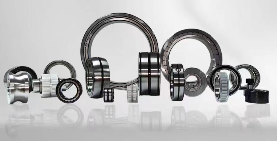
Bearing Insulation: The Ultimate Guide to Preventing Electrical Erosion in Bearings
Bearing insulation is a critical engineering solution designed to prevent electrical current from passing through rolling element bearings. In modern industrial applications, especially those involving variable frequency drives VFDs, stray electrical currents can cause severe damage known as electrical erosion or fluting. By effectively blocking these currents, bearing insulation extends equipment lifespan, reduces maintenance costs, and improves overall system reliability. This guide covers everything you need to know about insulated bearings, from materials to installation.
1、Insulated bearing types2、Bearing insulation resistance
3、Ceramic coated bearings
4、Shaft grounding rings
5、Electrical erosion prevention
1、Insulated bearing types
There are several primary types of insulated bearings available in the market, each designed for specific application requirements. The most common type is the hybrid ceramic bearing, which uses ceramic rolling elements such as silicon nitride Si3N4 combined with steel rings. These bearings offer excellent electrical insulation properties because ceramic materials are non-conductive. Another popular type is the coated bearing, where a thin layer of insulating material is applied to the outer or inner ring surface. Common coating materials include aluminum oxide Al2O3, ceramic coatings, and specialized polymer films. These coatings typically provide insulation resistance values exceeding 1000 megaohms. Additionally, there are fully insulated bearings that feature both ceramic rolling elements and insulating rings made from materials like PEEK or specialty composites. For extremely high voltage applications, manufacturers produce bearings with multiple layers of insulation, combining ceramic coatings with additional polymer barriers. The selection of the right insulated bearing type depends on factors such as operating voltage, speed, load conditions, and environmental factors like temperature and humidity. Hybrid ceramic bearings are particularly effective in high-speed applications because they generate less heat and have lower friction coefficients. Coated bearings are more cost-effective for retrofitting existing equipment where space constraints exist. Some specialized designs include insulated bearing housings that isolate the entire bearing assembly from the motor frame. Understanding these different types allows engineers to choose the most appropriate solution for their specific electrical protection needs. It is also important to consider the bearing's dynamic load rating and fatigue life when selecting an insulated bearing type, as some coatings may reduce the bearing's load capacity slightly. Regular inspection and testing of insulation resistance are recommended to ensure the insulation layer remains intact over time.
2、Bearing insulation resistance
Bearing insulation resistance is a critical parameter that determines how effectively a bearing prevents electrical current flow. This resistance is typically measured in megaohms MΩ and should be tested using a megohmmeter at specified voltage levels, usually 500V or 1000V DC. Industry standards recommend that insulated bearings maintain a minimum insulation resistance of 1000 MΩ for new installations. However, this value can decrease over time due to contamination, moisture ingress, mechanical wear, or degradation of the insulating material. The resistance measurement is taken between the bearing's inner and outer rings, or between the bearing and the housing. Factors affecting insulation resistance include temperature, humidity, and the presence of conductive contaminants such as carbon dust or metal particles. For applications involving high-frequency switching from VFDs, the insulation must withstand not only the fundamental voltage but also high-frequency voltage spikes that can exceed several thousand volts. The dielectric strength of the insulating material is equally important, typically expressed in volts per mil or kilovolts per millimeter. Common insulating materials like aluminum oxide coatings have dielectric strengths exceeding 10 kV/mm. Regular monitoring of insulation resistance is essential for predictive maintenance programs. A sudden drop in resistance may indicate coating damage or contamination that requires immediate attention. It is also important to note that insulation resistance can be affected by the bearing's operating temperature, as most insulating materials have reduced resistance at higher temperatures. Proper installation techniques, including clean mounting surfaces and appropriate sealing, help maintain optimal insulation resistance throughout the bearing's service life. Engineers should consult manufacturer specifications for recommended testing procedures and acceptable resistance thresholds for their specific applications.
3、Ceramic coated bearings
Ceramic coated bearings represent one of the most effective and widely adopted solutions for electrical insulation in rotating machinery. The coating process typically involves applying a thin layer of ceramic material, most commonly aluminum oxide Al2O3, to the outer diameter or bore of the bearing ring using plasma spray or physical vapor deposition PVD techniques. This ceramic layer provides excellent electrical insulation properties while maintaining the bearing's dimensional accuracy and mechanical performance. The typical coating thickness ranges from 100 to 300 micrometers, which is sufficient to provide insulation resistance exceeding 1000 MΩ even under harsh operating conditions. Ceramic coatings offer several advantages over other insulation methods. They are highly resistant to thermal shock, can withstand operating temperatures up to 500 degrees Celsius, and exhibit excellent adhesion to steel substrates. The coating also provides enhanced corrosion resistance and wear protection, extending the bearing's service life in aggressive environments. However, ceramic coated bearings do have some limitations. The coating can be brittle and may crack under excessive mechanical stress or improper handling. Special care is needed during installation to avoid impact damage to the coated surface. Additionally, these bearings typically cost more than standard bearings due to the specialized coating process. Applications for ceramic coated bearings include electric motors, generators, wind turbines, railway traction systems, and industrial pumps where electrical erosion is a concern. Recent advancements in coating technology have led to the development of multi-layer ceramic coatings that combine different materials to optimize both insulation and mechanical properties. Some manufacturers now offer hybrid solutions combining ceramic coatings with ceramic rolling elements for maximum protection. When selecting ceramic coated bearings, it is important to consider the specific voltage rating required, the operating temperature range, and the mechanical loads the bearing will experience. Proper storage and handling procedures must be followed to prevent coating damage before installation.
4、Shaft grounding rings
Shaft grounding rings are an alternative or complementary solution to bearing insulation for preventing electrical damage in rotating equipment. These devices work by providing a low-resistance path for stray electrical currents to flow from the rotating shaft to the ground, bypassing the bearings entirely. A typical shaft grounding ring consists of conductive fibers or brushes that make continuous contact with the rotating shaft surface. The fibers are usually made from materials like carbon, copper, or silver-impregnated polymers, designed to maintain good electrical contact while minimizing friction and wear. The grounding ring assembly is mounted around the shaft, typically at the non-drive end of the motor, and connected to the motor frame or earth ground through a heavy-duty cable. One of the main advantages of shaft grounding rings is that they protect all bearings in the system, not just the insulated bearing, by preventing voltage buildup on the shaft. They are particularly effective in applications with VFDs where high-frequency common-mode voltages are present. However, shaft grounding rings require regular maintenance to ensure proper operation. The conductive fibers can wear down over time, become contaminated with oil or debris, or lose contact pressure. Typical maintenance intervals range from 6 to 12 months depending on operating conditions. Some advanced designs include monitoring capabilities that provide feedback on contact resistance and remaining brush life. The effectiveness of a shaft grounding ring depends on proper installation and grounding system design. The grounding cable must have sufficient cross-sectional area to handle the expected current levels, and the connection to earth ground must have very low impedance. In some applications, multiple grounding rings may be installed at different locations along the shaft for optimal protection. Combining shaft grounding rings with bearing insulation provides the highest level of protection against electrical erosion. This dual approach ensures that even if one system fails or degrades, the other continues to provide protection. When selecting a shaft grounding ring, engineers should consider shaft speed, available mounting space, environmental conditions, and the specific electrical characteristics of the drive system.
5、Electrical erosion prevention
Electrical erosion prevention in bearings requires a comprehensive approach that addresses the root causes of stray currents and implements multiple protection strategies. The primary mechanism of electrical erosion occurs when electrical current passes through the bearing's rolling elements and raceways, causing localized heating and material transfer. This process creates characteristic washboard-like patterns called fluting on the raceway surfaces, leading to increased vibration, noise, and premature bearing failure. The most effective prevention strategy is to eliminate or minimize the source of stray currents at the system level. This involves proper motor and drive installation, including correct grounding of the motor frame, drive enclosure, and all associated cabling. Using shielded cables with proper termination techniques can significantly reduce electromagnetic interference and common-mode currents. Bearing insulation, whether through hybrid ceramic bearings or coated bearings, provides a direct barrier to current flow through the bearings. However, insulation alone may not be sufficient if voltage levels exceed the insulation's dielectric strength or if the insulation becomes compromised over time. Shaft grounding rings offer a parallel protection path by diverting currents away from the bearings. For critical applications, a combined approach using both insulated bearings and shaft grounding rings provides redundancy and maximum protection. Additional preventive measures include using conductive grease that can help dissipate small currents, installing filters on VFD outputs to reduce high-frequency voltage spikes, and maintaining proper motor alignment to minimize mechanical stress on bearings. Regular condition monitoring through vibration analysis, insulation resistance testing, and shaft voltage measurement helps detect early signs of electrical erosion before catastrophic failure occurs. Predictive maintenance programs should include scheduled inspections of insulation resistance and shaft grounding system performance. It is also important to consider the entire electrical system design, including proper cable routing, separation of power and control cables, and use of common-mode chokes where necessary. Training maintenance personnel to recognize the signs of electrical erosion and understand the importance of proper grounding practices is essential for long-term prevention success.
These five critical aspects of bearing insulation types, insulation resistance, ceramic coatings, shaft grounding rings, and electrical erosion prevention form a complete framework for protecting rotating equipment from electrical damage. Understanding how each element works and how they complement each other is essential for engineers and maintenance professionals. By implementing a combination of insulated bearings, proper grounding techniques, and regular monitoring, you can significantly extend equipment life and reduce unplanned downtime. The choice between different insulation methods depends on your specific application requirements, voltage levels, operating conditions, and budget constraints. For most modern VFD-driven systems, a layered protection approach provides the best results. As technology continues to advance, new materials and designs are making bearing insulation more effective and affordable than ever before.
In conclusion, bearing insulation is an indispensable technology for modern industrial applications where electrical currents threaten bearing reliability. Whether you choose hybrid ceramic bearings, ceramic coated bearings, shaft grounding rings, or a combination of methods, the key is to understand your system's electrical characteristics and implement appropriate protection measures. Regular testing and maintenance ensure that insulation systems remain effective throughout their service life. By prioritizing bearing insulation in your equipment design and maintenance strategy, you protect not only the bearings themselves but also the productivity and profitability of your entire operation. The investment in proper insulation pays dividends through reduced downtime, lower replacement costs, and improved equipment performance over the long term.



 8613869596835