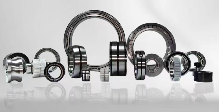
High Precision Cylindrical Roller Bearings: The Ultimate Guide to Design, Applications, and Selection
Cylindrical roller bearings are a critical component in modern industrial machinery, designed to handle high radial loads and operate at high speeds. Their unique design, featuring rollers that are longer than their diameter, provides a large contact area with the raceways, resulting in exceptional load-carrying capacity. These bearings are widely used in applications such as gearboxes, electric motors, and rolling mills, where reliability and performance are paramount. Understanding their structure, types, and applications is essential for engineers and procurement professionals seeking to optimize equipment performance and longevity.
1. Cylindrical roller bearing design2. Cylindrical roller bearing load capacity
3. High speed cylindrical roller bearing
4. Single row cylindrical roller bearing
5. Cylindrical roller bearing applications
1. Cylindrical roller bearing design
The design of a cylindrical roller bearing is fundamental to its performance and application versatility. Unlike ball bearings, which use spherical rolling elements, cylindrical roller bearings utilize cylindrical rollers. These rollers are guided by a cage or a flange on the inner or outer ring. The primary design consideration is the ratio of roller length to diameter, which typically ranges from 1:1 to 4:1. This elongated shape provides a line contact between the roller and the raceway, as opposed to the point contact found in ball bearings. This line contact significantly increases the bearing's radial load capacity. The internal geometry, including roller crowning and raceway profile, is meticulously engineered to manage stress distribution and prevent edge loading, which can lead to premature failure. Many designs incorporate a separable outer ring, facilitating easy mounting and dismounting, especially in applications where the shaft and housing have different thermal expansion rates. Lubrication pathways are also integrated into the design, with features like lubrication grooves and holes in the rings or cage to ensure effective oil or grease flow. The cage material, often steel, brass, or polyamide, is chosen based on operating speed, temperature, and lubrication conditions. Advanced finite element analysis (FEA) is now commonly used to optimize the design for specific load, speed, and environmental conditions, ensuring maximum durability and minimal friction. The design also considers the bearing's radial internal clearance, which is critical for accommodating thermal expansion and ensuring proper operation under load.
2. Cylindrical roller bearing load capacity
The load capacity of a cylindrical roller bearing is one of its most defining characteristics, particularly its exceptional ability to handle high radial loads. The basic dynamic load rating (C) and static load rating (C0) are key parameters defined by ISO standards. The dynamic load rating indicates the load under which the bearing can achieve a rated life of one million revolutions. Cylindrical roller bearings typically have a dynamic load rating that is 30% to 50% higher than a comparable size deep groove ball bearing, due to the line contact of the rollers. The static load rating is the maximum load the bearing can withstand without permanent deformation. For cylindrical roller bearings, this is also very high. It is important to note that most standard cylindrical roller bearings have a limited axial load capacity, typically only able to handle small axial loads or misalignment. However, specialized designs, such as those with flanges on both rings, can accommodate moderate axial loads. The load capacity is influenced by factors such as the number and size of rollers, the length of the rollers, and the hardness and cleanliness of the steel. Modern bearing steels, like 100Cr6 (SAE 52100), are vacuum-degassed to reduce impurities, significantly enhancing fatigue life under heavy loads. Proper mounting and alignment are crucial to achieving the rated load capacity. Misalignment can cause uneven load distribution, drastically reducing the bearing's effective life. Engineers must carefully calculate the equivalent dynamic load (P) considering both radial and any axial components to accurately predict bearing life using the L10 or L10h formulas. Additionally, operating conditions such as temperature, contamination, and lubrication quality can derate the load capacity, requiring the application of safety factors in critical designs.
3. High speed cylindrical roller bearing
High speed cylindrical roller bearings are specifically engineered to operate at elevated rotational speeds, often exceeding 10,000 RPM, while maintaining stability and low heat generation. Achieving high-speed performance requires careful optimization of several design elements. The cage design is paramount; lightweight, high-strength cages made from machined brass or polyamide (PA66) are preferred over stamped steel cages because they reduce inertia and improve lubrication flow. Polyamide cages, in particular, offer excellent sliding properties and can run at higher speeds with grease lubrication. The roller geometry is also critical. High-speed bearings often feature smaller diameter rollers with a higher length-to-diameter ratio to reduce centrifugal forces. The rollers are also precision-ground and honed to achieve extremely tight tolerances for roundness and surface finish, minimizing vibration. Internal clearance is carefully selected, often with a C3 or C4 clearance, to allow for thermal expansion at high speeds without causing preload. Lubrication becomes a critical challenge at high speeds. Oil-air lubrication or oil mist systems are commonly used to deliver a precise amount of lubricant to the rolling contacts while minimizing churning losses. Grease lubrication is possible but requires specialized high-speed greases with a low base oil viscosity and a stable thickener. The bearing rings are often made from through-hardened or case-hardened steels that maintain hardness at elevated temperatures. Advanced surface treatments, such as DLC (Diamond-Like Carbon) coatings, can further reduce friction and wear. High-speed applications include machine tool spindles, aircraft jet engines, and high-speed compressors. In these environments, the bearing must also be able to handle residual unbalance and dynamic loads without skidding or smearing, which can be a failure mode at very high speeds.
4. Single row cylindrical roller bearing
The single row cylindrical roller bearing is the most common and widely used type within the cylindrical roller bearing family. Its simple yet robust design consists of a single row of cylindrical rollers arranged between an inner and outer ring. This design is optimized for high radial load capacity and high-speed operation. The rollers are typically guided by a cage, which maintains proper spacing and prevents roller-to-roller contact. The key advantage of the single row design is its ability to accommodate significant radial displacement (axial expansion) of the shaft relative to the housing, making it an excellent choice for non-locating bearing positions in a shaft system. Most single row bearings are of the NU or N type, which have flanges on only one ring, allowing the shaft to float axially. This prevents axial forces from being transmitted between the shaft and housing, which is critical in applications with thermal expansion, such as long shafts in paper machines or conveyors. The NJ type, with flanges on both rings, can also handle moderate axial loads in one direction. Single row bearings are available in a wide range of sizes, from miniature bearings for small electric motors to massive bearings for rolling mill necks. They are relatively easy to mount and dismount, especially the separable designs where the inner ring with rollers and cage can be removed independently. The load capacity of a single row bearing is directly proportional to the number and size of the rollers. For applications requiring even higher radial load capacity, a double row or full complement design might be considered, but the single row offers the best balance of speed, load, and simplicity for most general industrial applications.
5. Cylindrical roller bearing applications
Cylindrical roller bearings are indispensable across a vast spectrum of industrial applications, thanks to their high radial load capacity, high-speed capability, and durability. In the automotive industry, they are used in transmissions, differentials, and wheel hubs, where they handle the radial loads from gears and vehicle weight. In electric motors, particularly those in industrial pumps, fans, and compressors, cylindrical roller bearings support the rotor and handle belt tension or coupling forces. The gearbox industry is a major consumer, using these bearings for input, output, and intermediate shafts to manage the high radial forces generated by gear meshing. In heavy machinery like rolling mills, they support the massive work rolls and backup rolls, enduring extreme loads and harsh environments. Machine tool spindles rely on high-speed cylindrical roller bearings for precision and rigidity during cutting operations. The aerospace sector uses them in aircraft engines, helicopter transmissions, and landing gear systems, where reliability under extreme conditions is non-negotiable. In the energy sector, they are found in wind turbine gearboxes, hydroelectric turbines, and oil drilling equipment. Furthermore, cylindrical roller bearings are used in railway axle boxes, where they must withstand heavy radial loads and vibration. Their versatility also extends to material handling equipment, printing presses, and textile machinery. The choice of bearing type, size, and internal design is always tailored to the specific load, speed, temperature, and lubrication conditions of each application, making cylindrical roller bearings a cornerstone of modern mechanical engineering.
From the robust single row designs used in electric motors to the specialized high-speed versions for machine tool spindles, the versatility of cylindrical roller bearings is unmatched. Understanding their design principles, load capacities, and suitability for high-speed operation is crucial for any engineer or procurement specialist. The applications span from heavy industries like steel rolling to precision sectors like aerospace. Whether you need a bearing for a gearbox, a pump, or a wind turbine, the performance and longevity of your machinery depend on selecting the right cylindrical roller bearing. Explore how these components can solve your engineering challenges and improve operational efficiency.
In summary, cylindrical roller bearings are a cornerstone of modern mechanical engineering, offering unparalleled radial load capacity and high-speed performance across countless industries. From their meticulous design, which optimizes line contact and stress distribution, to their impressive dynamic and static load ratings, these bearings are built for durability. Specialized variants, such as high-speed bearings with lightweight cages, push the boundaries of rotational speed. The ubiquitous single row design provides a perfect balance of load, speed, and simplicity, making it the go-to choice for many applications. Their deployment in critical sectors like automotive, aerospace, energy, and heavy machinery underscores their reliability. Proper selection, mounting, and lubrication are essential to unlocking their full potential. Ultimately, understanding the specific demands of your application and choosing the appropriate cylindrical roller bearing will lead to enhanced machine performance, reduced downtime, and lower total cost of ownership.



 8613869596835