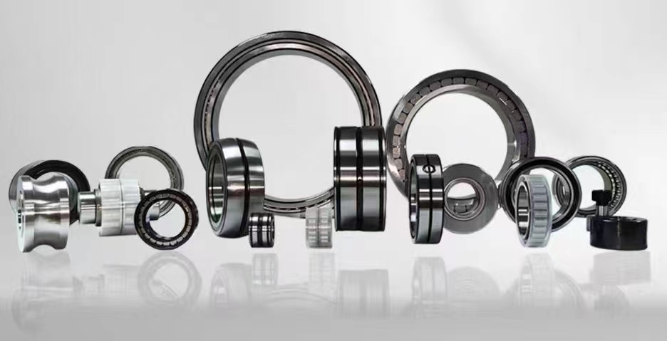
Angular Contact Ball Bearing: Precision Engineering for High-Speed Applications
Angular contact ball bearings are precision rolling element bearings designed to support combined radial and axial loads simultaneously. Unlike deep groove ball bearings, these bearings feature a specific contact angle between the balls and the raceways, typically ranging from 15 to 40 degrees. This unique geometry enables them to handle significant thrust loads in one direction, making them indispensable in high-speed and high-precision applications such as machine tool spindles, pumps, compressors, and automotive transmissions. The ability to operate at elevated speeds with minimal friction and heat generation is a defining characteristic of angular contact ball bearings, ensuring reliable performance in demanding industrial environments.
1、Angular Contact Ball Bearing Design2、Single Row Angular Contact Bearing
3、Double Row Angular Contact Bearing
4、Bearing Contact Angle
5、Bearing Preload
6、Bearing Mounting and Arrangement
7、Bearing Cage Materials
1、Angular Contact Ball Bearing Design
The design of angular contact ball bearings is a sophisticated engineering feat centered on the concept of a defined contact angle. The inner and outer ring raceways are offset relative to each other in the axial direction, creating a line of contact between the ball and the raceway that forms a specific angle with the radial plane. This contact angle is a critical parameter, typically standardized at 15 degrees (C), 25 degrees (AC), or 40 degrees (B) for most industrial bearings. The larger the contact angle, the greater the axial load capacity, but at the expense of reduced high-speed capability. The balls are guided by a cage, which can be made from pressed steel, machined brass, polyamide (nylon), or phenolic resin, depending on the operating conditions. The internal geometry, including raceway curvature and ball size, is optimized to minimize stress concentration and maximize fatigue life. Precision grades such as P4, P5, or P2 are available for applications requiring extreme accuracy, like machine tool spindles. Lubrication is a key design consideration; grease is common for moderate speeds, while oil-air or oil-mist lubrication systems are employed for ultra-high-speed applications. The design also incorporates features to facilitate mounting, such as snap rings or locating slots, ensuring proper axial positioning within the housing. Understanding these design elements is essential for selecting the correct bearing for a given mechanical system, as they directly influence performance, reliability, and service life.
2、Single Row Angular Contact Bearing
Single row angular contact ball bearings are the most fundamental configuration within this bearing family. They consist of one row of balls arranged between a single inner and outer ring, with a defined contact angle. The primary characteristic of a single row bearing is that it can support axial loads in only one direction, in addition to radial loads. Therefore, to handle bidirectional axial loads, two single row bearings are typically mounted together in a back-to-back (DB), face-to-face (DF), or tandem (DT) arrangement. The load capacity of a single row bearing is high relative to its size, making it a popular choice for applications where space is limited but high rigidity and speed are required. Common applications include machine tool spindles, where multiple single row bearings are paired to achieve the desired stiffness and axial load capacity. Gearboxes also use single row angular contact bearings to support the gear shafts, particularly where high axial thrust is present. In the automotive industry, these bearings are found in wheel hubs and transmission systems. The single row design is relatively simple to manufacture and inspect, contributing to cost-effectiveness. However, careful attention must be paid to the mounting arrangement and preload to ensure proper load distribution and prevent premature failure. The choice of cage material and lubrication method is also critical, especially in high-speed environments where centrifugal forces can cause cage instability. Single row angular contact bearings offer an excellent balance of performance, cost, and versatility, making them a standard solution in many mechanical designs.
3、Double Row Angular Contact Bearing
Double row angular contact ball bearings are a specialized design that integrates two rows of balls within a single outer ring and a single inner ring, effectively forming a matched pair of single row bearings. This configuration inherently provides the ability to support axial loads in both directions, eliminating the need for separate bearing pairs. The two rows are arranged with opposing contact angles, typically 25 degrees each, which creates a rigid, preloaded unit that can handle high radial and axial loads from either direction. The compact design of double row bearings saves axial space and simplifies mounting, as they are pre-adjusted and require no additional shimming or preloading during installation. They are commonly used in applications where space constraints are severe, such as in automotive alternators, water pumps, and electric motors. The double row design also offers higher radial load capacity compared to two separate single row bearings of the same size, due to the shared raceway geometry. However, the operating speed is generally lower than a comparable pair of single row bearings because of the increased internal heat generation and the complexity of the cage design. Lubrication is critical; grease is often used for life-time sealed versions, but oil circulation may be necessary for high-speed or high-temperature applications. The internal clearance is pre-set by the manufacturer, so the user must select the correct clearance class (C2, CN, C3, etc.) based on the operating conditions. Double row angular contact bearings are a robust and efficient solution for applications requiring bidirectional axial load support in a compact package.
4、Bearing Contact Angle
The contact angle is the most defining parameter of an angular contact ball bearing. It is the angle formed between the line joining the points of contact of the ball with the inner and outer raceways and a plane perpendicular to the bearing axis. This angle is not a fixed geometry but is determined by the raceway curvature and the relative axial displacement of the rings. The standard contact angles are 15 degrees (C), 25 degrees (AC), and 40 degrees (B). A 15-degree contact angle is optimized for high-speed applications where radial loads dominate, such as in high-speed spindles. The smaller angle reduces centrifugal forces and heat generation, allowing for higher rotational speeds. A 25-degree contact angle offers a balance between axial load capacity and speed, making it a versatile choice for many general engineering applications. A 40-degree contact angle is designed for applications requiring high axial load capacity, such as in heavy-duty machine tools or axial compressors. The contact angle directly influences the load distribution among the balls, the stiffness of the bearing, and the limiting speed. As the contact angle increases, the axial load capacity and stiffness increase, but the maximum permissible speed decreases. The contact angle also affects the internal clearance and preload characteristics. When bearings are mounted in pairs, the contact angle determines the effective load center, which is crucial for calculating the overhung loads on shafts. Understanding the contact angle is essential for engineers to select the correct bearing for a specific load and speed profile, ensuring optimal performance and longevity.
5、Bearing Preload
Bearing preload is a critical technique used in angular contact ball bearing applications to eliminate internal clearance, increase stiffness, and improve rotational accuracy. Preload involves applying a controlled axial force to the bearing, which compresses the balls against the raceways, removing any radial or axial play. This is particularly important for applications like machine tool spindles, where even micron-level displacement can affect machining precision. Preload can be applied in two primary ways: by using specially matched bearing pairs with a predetermined axial offset (preload by design) or by using springs or hydraulic cylinders to apply a constant force (constant pressure preload). The amount of preload must be carefully calculated; too little preload leaves clearance, causing vibration and reduced stiffness, while excessive preload increases friction, heat generation, and wear, leading to premature failure. Preload also affects the bearing's operating temperature and speed capability. In high-speed applications, preload is often reduced to minimize heat, using techniques like light preload or variable preload systems. The preload value is typically specified by the bearing manufacturer based on the application requirements. For matched bearing sets (DB, DF, DT), the preload is built into the bearing pair during manufacturing and is indicated by a code (e.g., L, M, H for light, medium, heavy preload). Proper preload selection and application are essential for achieving optimal performance, especially in precision machinery where rigidity and accuracy are paramount.
6、Bearing Mounting and Arrangement
The mounting and arrangement of angular contact ball bearings are crucial for achieving the desired load capacity, stiffness, and operational life. Because single row bearings can only support axial loads in one direction, they must be mounted in pairs to handle bidirectional axial forces. The three standard arrangements are back-to-back (DB), face-to-face (DF), and tandem (DT). In a DB arrangement, the load lines of the two bearings converge outside the bearing pair, providing high stiffness and resistance to moment loads. This is the most common arrangement for machine tool spindles. In a DF arrangement, the load lines converge inside the bearing pair, offering moderate stiffness but better thermal compensation. The DT arrangement places the bearings with load lines in the same direction, effectively doubling the axial load capacity in one direction, but requiring a separate bearing for the opposite direction. Double row bearings are pre-assembled with the correct arrangement, simplifying mounting. Proper mounting also involves accurate shaft and housing fits, correct lubrication, and appropriate seals to prevent contamination. The axial location of the bearings must be fixed to prevent axial movement under load. Preload is often applied during mounting using shims, spacers, or locknuts to achieve the desired stiffness. Incorrect mounting can lead to misalignment, excessive heat, noise, and reduced bearing life. Therefore, following manufacturer recommendations for mounting procedures, torque values, and clearance adjustments is essential for reliable operation.
7、Bearing Cage Materials
The cage, also known as the retainer or separator, is an integral component of angular contact ball bearings. Its primary function is to maintain uniform spacing between the balls, prevent them from contacting each other, and guide them through the load zone. The choice of cage material significantly influences the bearing's performance, speed capability, and suitability for different environments. Common cage materials include pressed steel, machined brass, polyamide (nylon), and phenolic resin. Pressed steel cages are economical and offer good strength, making them suitable for general-purpose applications. Machined brass cages provide excellent wear resistance and can operate at higher speeds due to their superior thermal conductivity and lower friction. Polyamide cages are lightweight, corrosion-resistant, and have excellent sliding properties, making them ideal for high-speed applications where low inertia is critical. However, they have temperature limitations. Phenolic resin cages are used in ultra-high-speed applications, such as aircraft engines and precision spindles, because of their high strength-to-weight ratio and dimensional stability. The cage design also varies; some cages are ball-riding, while others are ring-riding. The material and design must be selected based on operating conditions, including speed, temperature, lubrication type, and contamination levels. In high-speed applications, the cage must withstand high centrifugal forces and maintain its shape to prevent ball skidding. The use of advanced materials like polyetheretherketone (PEEK) is becoming more common in specialized applications due to their superior performance. Proper cage selection is essential for maximizing bearing life and reliability.
Angular contact ball bearings are a cornerstone of modern precision machinery, offering unmatched performance in applications requiring high speed, high rigidity, and combined load support. The seven key aspects discussed—design, single row vs double row configurations, contact angle, preload, mounting arrangements, and cage materials—form the complete knowledge base for selecting, applying, and maintaining these bearings. Whether you are an engineer designing a new spindle, a maintenance technician troubleshooting a gearbox, or a procurement specialist sourcing components, understanding these factors ensures you choose the right bearing for your specific needs. The versatility of angular contact ball bearings makes them suitable for industries ranging from aerospace and automotive to medical devices and robotics. By mastering the principles outlined here, you can optimize machine performance, reduce downtime, and extend equipment life. For further technical guidance, consult bearing manufacturer catalogs or contact our engineering team for personalized support.
This comprehensive guide has covered the fundamental aspects of angular contact ball bearings, from their unique design and load capabilities to the critical details of preload, mounting, and cage selection. By understanding the seven key topics—design, single row and double row configurations, contact angle, preload, mounting arrangements, and cage materials—you now have a solid foundation for making informed decisions. Angular contact ball bearings are essential components in high-speed spindles, automotive transmissions, industrial pumps, and many other precision systems. Their ability to handle combined loads with minimal friction sets them apart from other bearing types. We encourage you to apply this knowledge in your next project to enhance reliability and performance. For more detailed specifications, installation guides, or product inquiries, please explore our product pages or contact our support team. Thank you for reading, and we look forward to assisting you with your bearing needs.



 8613869596835